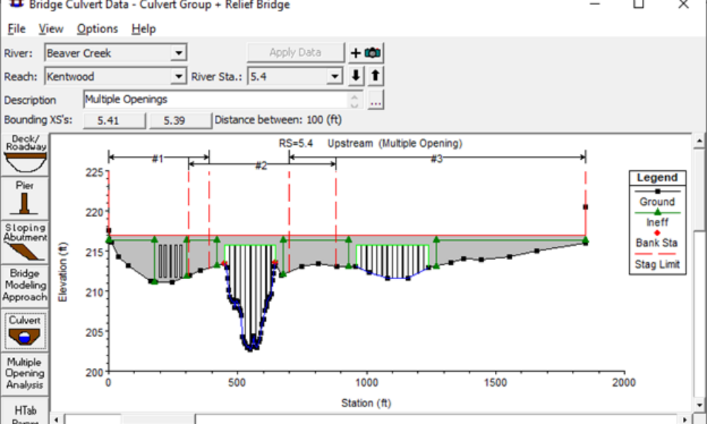
Multiple Opening Analysis
Did you know that if you have a bridge opening and one or more culverts at a single river crossing a Multiple Opening Analysis is required?
Your computational mesh is what will allow you to do 2D modeling in HEC-RAS. Think of a mesh as a net that you drape over your terrain. The continuous properties of the “infinite” terrain are then discretized onto the mesh so that computations can be made over a finite domain. Here in the geometry editor, we can see the computational mesh “draped” over the terrain. Notice that the mesh remains within the perimeter of the terrain. This is required for HEC-RAS. RAS is able to work with structured or unstructured meshes with cells that have up to eight sides. Typically you’ll begin with a Cartesian or rectilinear structured mesh and where you add more detail and resolution, you’ll have unstructured (irregular) zones within your mesh. Boundary cells will also exhibit unstructured characteristics where RAS works to fit the mesh to the mesh perimeter.
Before building your mesh, it can be useful to include a background image of your terrain so that you can make sure you draw your grid within the bounds of your terrain. The background image will also give you a clue about areas in your 2D grid that might need more or less detail. The background image has to be created external to HEC-RAS and must be accompanied by a world file. More information about world files can be found here: http://webhelp.esri.com/arcims/9.2/general/topics/author_world_files.htm
Use the 2D Flow Area button at the top of the geometry schematic to draw a new 2D area. This is drawn exactly the same way storage areas are drawn. Single click the points to define a polygon shape, staying within the bounds of the terrain (very important), and to complete the area, double click.
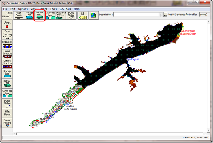
Once a 2D area has been defined, click on the 2D Flow Area editor button to set up the mesh. The first windows provides the user options for Manning’s n value for the 2D Area. Only 1 n value can be used for now in the 5.0 beta version of HEC-RAS for a 2D Area, but future versions will allow multiple n value definition for a single 2D Flow area. The tolerance input boxes allows the user to have some control on how much data goes into each of the cells on the soon-to-be-created 2D grid. The defaults usually work very well for the tolerance inputs. Typically you’ll enter the Manning’s n value and then click the “Generate Computation points on regular interval. Then go ahead and define the grid cell size (both width, DX, and height, DY). The starting offset point is optional. Default is to leave it at 0,0. Then click “Generate Points in 2D Flow Area, and HEC-RAS will build a structured mesh of constant cell size (this can be adjusted later).
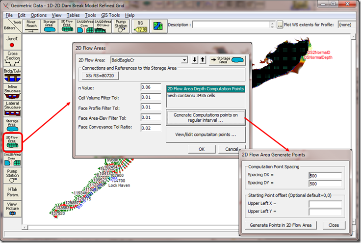
Here we can see the mesh that was created with 500 ft X 500 ft spacing. Notice that the majority of the mesh was created with 500-ft by 500-ft square cells, but around the perimeter of the 2D area, RAS automatically creates irregularly shaped cells to fit the edges. These should always be checked after the mesh is created to make sure the edge cells are suitable. Look for cells with multiple centers, or cells that are not generally the same size and aspect ratio as the others (like the example highlighted above).
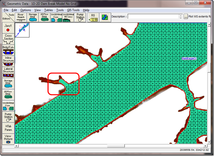
You can fine tune your mesh (either correcting unsuitable boundary cells or adding more detail/resolution) by using the “Move”, “Add”, and “Remove” tools in the Edit menu of the Geometry Schematic. After you select Edit…Move Points/Objects, you can click and drag any of the cell center points. Once you “de-select” Move Points/Objects, HEC-RAS will redraw the grid based on the new, manual placement of centers.
In addition to moving cell centers, you can add more cell centers to your mesh where you need more detail, and remove cell centers where you need less detail. For example, in this narrow connection between two flooded areas, we want more definition to better simulate the flow through here. Manually click some points where more definition is needed. Once “Add Points” is unchecked, HEC-RAS will automatically redraw the grid. Where you move points or add more points, the mesh will look a lot less structured. 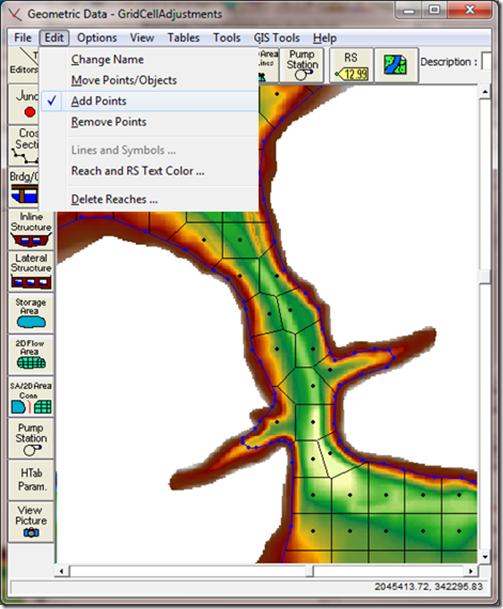
Look closely at this last figure. We have a nice structured grid in the large floodplains to the northwest and southeast. The narrow connection between the two exhibits a very unstructured mesh with more detail. There are (at least) two things wrong with the grid. In fact, these two things will prevent RAS from running until they are resolved. Post a comment below and let me know what you think the errors are.
More information on 2D modeling in HEC-RAS can be found here: https://drive.google.com/file/d/0B_s8OLJOgOi0Nm5sdHFhSzFUYkk/edit?usp=sharing
Images in this post are from the Bald Eagle Creek Example Dam Break Study example data set. The Bald Eagle Creek Example Dam Break Study HEC-RAS model is provided courtesy of the Hydrologic Engineering Center and can be downloaded along with HEC-RAS Version 5.0 beta here: http://hecrasmodel.blogspot.com/2014/10/updated-hec-ras-version-50-beta-now.html
Comments
Anonymous
on September 16, 2014The error is the same for two of the problem areas… multiple cell centers in a single mesh element.
Valter Albino
on September 16, 2014Hello
This is a very useful and special post, thank you.
Perhaps the need to redraw the grid?
I see several points but no mesh on their locations (in the left and right sides of the narrow sector).
Chris G.
on September 16, 2014Congratulations Anonymous and Valter. You not only made it to the bottom of my post, but you got the answer correct!
Anonymous
on September 17, 2014This is a useful post. Thanks Chris! Another thing that I would like to know more about are the tolerances provided in RAS for each 2D mesh area in the model. For example the face conveyance tolerance ratio, when would you want to change that from the default and what effect would it have on the model results. Thanks for the great blog!
Chris Goodell
on September 17, 2014You're welcome! Typically the tolerances are changed from the default when you are having stability issues. With regard to the face conveyance tolerance, the result of changing it is more stability with a larger value, more accuracy with a smaller value. I might consider making the tolerance ratio larger if I'm seeing instabilities in the cells during a dynamic event. But my approach with the computational options and tolerances (both 1D and 2D) are to generally leave them alone and focus my efforts on geometric fixes. A lot of times, bumping up the tolerance level might actually allow you to accrue more error, which in and of itself can lead to numerical instabilities.
Anonymous
on September 17, 2014Thanks for the informative response and post Chris. I have a lot of questions about RAS 2D…
luis prieto
on May 14, 2015chris good day. can only be performed in the simulation area 2d stretch of a river regardless floodplains? project since my college thesis Floodplains not overflow and the water only stays in the stretch of the river and let me know if I can get results only from this area 2d creating computational mesh only the river.
thank you very much
SAMSEIHA UK
on October 17, 2016Hi Chris,
I have problem with Cell Size in Terrain Layer Property, In fact I have processed in ArcGIS with Raster Image with the resolution of 1Arc-Second Global (Source USGS). In 3D Analyst tool the cell (30×30) unit shown details in meters Unit, generating to Float type the scale are the same. When importing to New Terrain in HECRAS the Cell was decreased. What is your suggestion?
Ramesh Gautam
on April 7, 2017Hi Chris,
I am having problem on creating the grid. My study area is very narrow with a corner at one end. I am trying to fix the errors, however, it is almost impossible to fix. If I fix at one location, it appears to another location. While fixing at another location, it shifts back to another location. Just like cat and mouse game, the error keeps appearing. Any suggestion?
Chris Goodell
on April 7, 2017Try expanding your 2D area and rounding/smoothing out the corners. Try to avoid sharp angles and narrow protrusions in your 2D area. As long as your 2D area remains within your Terrain boundary, you can expand your 2D area outside the flooded area as much as you need to to have smooth rounded edges. Also, smaller cells will help.
Hemanth Sri
on April 24, 2017Hi Chris sir,
I want to determine the velocity distributions of every node at 5 meter( 16.04 ft) interval along the cross section of river reach.
Is their any availability in HEC-RAS to know the velocities at each and every point along the cross-section.
Thank you sir.
Chris Goodell
on May 1, 2017You can try using the velocity distribution option for cross sections and then max out the number of slices you use for each sub section. This won't allow you to discretely select the locations for velocity output across your cross section, but you should be able to get a very good spread.
Anonymous
on February 15, 2018Hi,
I've got a problem for which I haven't been able to find an answer.
The 2D flow area has been disconnected from, and moves in isolation of, the underlying map – despite no change (as far as I can tell) in the geographical extents.
Any tips to rectify this problem?
K.C.
on April 30, 2018Sir, I'm unable to generate 2D flow mesh on DEM format file for flow computation. Please help
Anonymous
on July 6, 2018Hello Chris Sir,
Is there a way we can get the X and Y coordinates of red dots? I am talking about the dots that shows the cells with more than 8 sides.
Thanks
Ahcene Aitabed
on March 12, 2019Hi Chris,
Can I add a river inside my mesh ?
I am trying to run a dam breach modeling, and my dam discharges into a tributary to another river, what I want to do is to put an initial flow in that river before it receives the flow from the dam.
Thanks a lot, you're doing an awesome work.
Chris Goodell
on March 12, 2019Hi Ahcene-
Yes you can have a river in your mesh. Use refinement regions to make sure you have at least 5 cells across your river. To have initial flow in your river, you need to start the 2D area out dry and run "initial conditions time" for a long enough period to fill up the river. The initial conditions time entry is in the unsteady flow analysis window under Options…Calculations Options and Tolerances, 2D Flow Options.
Prince
on June 10, 2019Hi Chris,
What is the limit on number of cells during mesh creation for 2D analysis?
Using 10m DEM, what is best cell dimension i.e. 10×10, 100×100 for flood map generation?
Thanks,
Prince
Chris G.
on June 14, 2019Hi Prince. There is no limit. At least not intentionally by HEC. However, in practical terms, you don't want so many cells that your model takes too long to run. I usually try to keep my cell count to below 10,000 if I want a really fast model. Sometimes it's unavoidable, and you just need a lot of cells. You'll learn pretty quickly how many cells is too many for your patience. The cell size is not so much a function of the DEM, but more of the desired accuracy in the hydraulics. You want to have small enough cells to pick up terrain features, but breaklines can be used to allow you to get those terrain features while still maintaining relatively large cells. You also want to try to avoid fragmentation in your results. So for steeper terrain, with smaller depths, you'll need smaller cells. And most importantly, to get the hydraulics correct, you want to target about 5 to 7 cells (minimum) across an important conveyance like a river or creek, or even in the floodplain in an area with higher velocities where you have some interest.
Unknown
on August 12, 2019Hi Chris,
I am struggling with the Hecras Model.
I am modelling the Dam Breach and my model took too long to run with so many errors.I am getting the repitative iteration due to the Large difference between Water Surface Elevation and Cell Number.
Unknown
on September 18, 2019Hi Chris,
How do you get your 2D Mesh to be transparent in your Geometry Editor, like in the last two photos? I'm trying to place a culvert but my 2D Mesh is solid green (like your other photos) and I can't see where the culvert is.
Thanks,
Midori
Chris G.
on September 23, 2019In the geometry window, go to View…View Options. And uncheck where it says "Fill in Storage Areas/2D Flow Areas."
Steve
on October 1, 2021I used breaklines and refinement regions in order to create a higher resolution mesh within the channels in my modeling domain. However, this approach has caused problems with computing the property tables. When computing property tables within RASMapper, I received the following error: “RAS index was out of range. Must be non-negative and less than the size of the collection.” When attempting to run an unsteady flow analysis, I received the following error: “Unable to compute face tables. The terrain associated with this geometry does not completely cover the 2d Flow Area ‘Perimeter 1’. See face(s) #(…,…,…)”. I assume that something related to the higher resolution mesh areas within and adjacent to the channels is preventing the creation of the hydraulic tables. Do you have any advice about how to resolve this issue?
Chris Goodell
on October 6, 2021That’s interesting Steve. First make sure that your 2D mesh is completely within the extents of the terrain it is associated with. And make sure you don’t have any cell violations (red dots). Beyond that, I’m not sure what the issue could be. Usually when I get stuck on an error like that, I try different resolutions of my refinement regions and breaklines to see if I can get beyond that error.
Hamza Khan
on January 30, 2023Hello sir, actually I am facing a problem with meshing, after entering computation points spacing it’s showing that the current mesh contains no computation points. Can you please help me out, sir
Add Your Comment