Multiple Opening Analysis
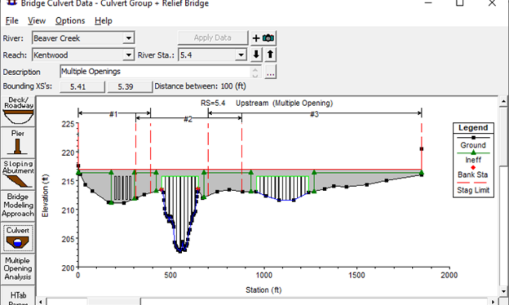
Did you know that if you have a bridge opening and one or more culverts at a single river crossing a Multiple Opening Analysis is required?
In 2D HEC-RAS models, when you want to see a water surface profile plot, similar to the classic 1D water surface profile plot, you need to use “Profile Lines” in RAS Mapper. Profile lines allow you to extract spatial results (Depth, Water Surface Elevation, Velocity, etc.) along the coordinates of the profile line in a nice, easy-to-view plot. One of the nice features in the 1D version of the plot is the ability to view computed water surfaces along levees if they’re represented as lateral structures in the model. This is a great way to check freeboard on a simulated levee. In 2D, there is no way to directly include the lateral structure on the profile line plot to compare with the water surface elevation. Furthermore, if there is any sinuosity in the river, and/or the levee doesn’t follow the orientation of the river centerline exactly, then the stationing of the levees won’t be consistent with the stationing of the river centerline (see Figure 1). This makes it difficult to compare water surface elevations along levees for the purposes of determining freeboard for various flood events.
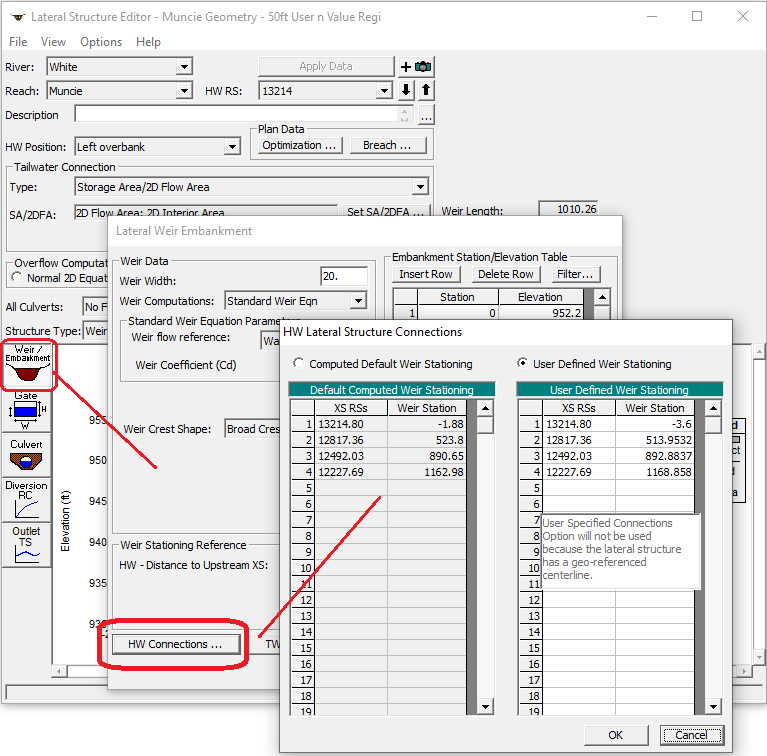
This blog post demonstrates a way to solve this problem using the Headwater (HW) Connections Table in the Lateral Structure editor with some simple VBA code. The HW Connections table is found in the Lateral Structure Editor in the Weir/Embankment section (Figure 2). This table is automatically created by HEC-RAS when a lateral structure is created and is used to associate lateral structure weir stationing with river stationing. This is necessary for RAS to determine which 1D cross sections are delivering flow to which 2D cells over the lateral structure. The following instructions assume you already have a working 2D model.

Figure 1. Example location where levee does not follow parallel to the river and the stationing of the levees would not be consistent with the river centerline stationing.

Figure 2. The HW Lateral Structure Connections Table
1. In RAS Mapper, create feature lines along the river centerline and the levees on each side of the river, making sure they are drawn upstream to downstream. These feature lines can then be imported to a dummy geometry file as a river centerline and lateral structures. Paste the coordinates of the feature line representing the river to the GIS coordinates of the river centerline in the geometry file. With the river centerline defined in the geometry file, add cross sections at the upstream-most end and the downstream-most end of the river, making sure that the downstream cross section is close enough to the end so it is assigned a stationing of exactly 0. To do this, you will need to zoom in very close to the river center line and adjust the location of the cross section, so it sits very near the end of the river centerline. Having this cross section at zero ensures that the entire river centerline can be used for interpolation. Save this geometry and then open it in the geometry editor.
2. Now add station-elevation points and n values to both cross sections in the cross-section editor, making simple rectangular sections. This is necessary, otherwise the cross sections can’t be interpolated; however, the shape of the cross section and the n value is unimportant for this process. The left and right bank stations should be set for the two cross sections as well and can be set to the end points. Using these cross sections, now you can interpolate cross-sections at the interval where you would like to have water surface elevation output. Using the “XS interpolation between two cross sections” tool, set the decimal places in the interpolated stations to 0 (to ensure that all cross sections are whole numbers), use a constant distance, and generate the cross sections for display as perpendicular segments to the reach invert.
3. The levees can now be added as lateral structures. First, in RAS Mapper, copy the coordinates of the profile lines of the levees. Moving back to the geometry editor, add two lateral structures in the lateral structure editor-one on each side of the river. The coordinates of the profile lines can be pasted in using the “Centerline GIS Coords…” table. The weir length needs to be adjusted to match the centerline length, and the weir width can be arbitrarily set to any number. Set the “headwater distance to upstream” to 0. With the levees now added, you can get all the information needed to start interpolating water surface elevations along the levees.

Figure 3. Levees added as lateral structures.
4. Create a excel spreadsheet to do the interpolations. You need 3 key pieces of information to be able to do this:
This data needs to be cleaned up a bit – blank rows in some of the above datasets, as well as rows with NaN values, must be removed. The asterisks from the end of the interpolated cross section values also need to be removed. One way this can be done is by writing up a short script, which simply loops through all of the cross sections and removes astrisks if they have them.

Figure 4. Example VBA script for removing asterisks from interpolated cross section values.
5. Next, you can interpolate the water surface elevation for the river stations associated with the left and right levee stationing. There are 3 key parts to this interpolation script (Figure 5).
a. Creating variables to store the values needed for interpolation, along with creating variables for some of the cells we want to return to. The return address is so that the interpolation continues to search for the next river station where it left off on the prior interpolation – just to speed up the code.
b. The “Do” loop will help to search through the river stationing associated with the water surface elevation. It goes through each station until it finds one just prior to the river station that you want to match with the levee.
c. The last section of the code will set the variables using linear interpolation, calculate the interpolated water surface elevation for the station using linear interpolation, and add the calculated value to the associated cell.
This script repeats this process for all the stations that we need water surface elevations for. After writing it, make sure to run it on the first few cells to test it and check your results before computing the entire column.

Figure 5. Example VBA script for interpolating water surface elevations along the river centerline.
6. You will need to write additional scripts, with updated cell locations and ranges, following the same setup to retrieve interpolated elevations for both the left and right levees at the river stationing associated with the levee stations (Figure 6).

Figure 6. Example VBA script for interpolating levee stationing along the river centerline (for the right levee).
For the results (Figure 7), you should plot the interpolated right levee elevation, the interpolated left levee elevation, and the interpolated water surface elevation in Excel, all against the original river stationing. This allows you to see where the water surface elevation is above or below the levees, along the length of the river.

Figure 7. Interpolated levee stationing and water surface elevations vs. elevation.
Comments
Ntokozo Xaba
on March 30, 2023Good Day,
I am interested in this course, can you kindly send me further information.
Thank you
Add Your Comment