May 24, 2024
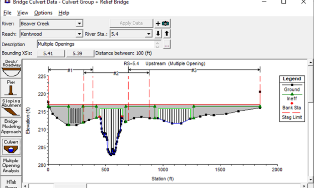
Multiple Opening Analysis
Did you know that if you have a bridge opening and one or more culverts at a single river crossing a Multiple Opening Analysis is required?
For a dam breach model, you’re probably looking at conditions where the water surface is cresting the road, most likely submerging the spillway. In this case (and assuming you’ll be breaching some other part of the embankment), I would treat the spillway and culvert as one structure-an inline structure in RAS. Model the culvert as a gate. You’ll have to either use a rectangular shape to approximate the culvert, or come up with a user-defined rating curve. The rating curve could be easily determined by setting up a different geometry file with this crossing modeled as a cmp pipe-arch culvert. Then run a number of different steady flows through it. This will give you a good rating curve. Then import it as a use-defined rating curve for your gate. Perhaps you increase the entrance loss coefficient slightly to account for energy loss as flow lines contract and expand over the spillway structure before entering the culvert.
Under normal flow conditions, I would set up two geometries-one with just the culvert, and one with just the spillway. Then look at the conditions you are most concerned with and pick the geometry that controls the flow at the structure (whichever geometry produces a higher headwater elevation for a given flow amount). If you really want to see a full unsteady flow simulation (where control is switching from spillway to culvert, and back to spillway, then you’ll have to break the model up into multiple simulations, with the end of the previous simulation used as the initial conditions for the next one (using a restart file). You’ll want to split the simulations up where control switches from spillway to culvert. This will take some trial and error work.


Comments
Andy
on October 11, 2010RAS only has pipe arch culvert property tables for corrugated metal. How would you model an rcpa culvert? When I enter the rise for an rcpa culvert, the corresponding span is off. Should I just use the size associated with the equivalent cmpa?
Chris G.
on October 12, 2010If the spans allowed in RAS are not consistent with the true spans of a particular culvert type, I would get the rise correct (this is more important, because it affects when hydraulic transitions take place), and adjust the Discharge coefficient to account for the different flow area. For example, if the span that RAS allows you to select is 2 meters (with a computed flow area of 1.6 m^2), but your culvert is really 2.1 meters wide (with a computed flow area of 1.8 m^2), then go with the 2 meter span, and adjust your coefficient up by a factor of the ratio between resulting flow areas (1.8/1.6 = 1.13). So if your true discharge coefficient is 0.6, then for the simulation, use a discharge coefficient of 0.68. Of course, if you're running an unsteady flow model, or multiple profiles in a steady flow model, you may have a different discharge coefficient for each profile (unless you are using a rectangular culvert). It's up to you which coefficient you should choose.
Anonymous
on August 8, 2013How to model a gate in front of a circular culvert.
Did it with a sluice gate in front of a culvert but I don't get the same resultats by hand calculations.
It's the effective area under the gate I think as it flows through a circular culvert. The end section of the gate isn't circular.
Should I do it separately as you mention?
Chris G.
on August 12, 2013Keep in mind that if you use a gate in RAS, it will use the gate equations, not the culvert equations, and visa versa. Please read up on both computational procedures in the hydraulic reference manual, so you can make sure you are reproducing what RAS does, when you do your hand calculations. Personally, I would try the same technique (model separately and see which one controls) if it's a steady flow model.
Steph
on October 23, 2018I am modelling a box culvert that has a weir halfway underneath it. There is a 1m drop between the upstream invert and the downstream invert of the culvert and therefore the height of the culvert is taller on the downstream side. How would you model this scenario in HEC-RAS? As a box culvert with a 1m drop on the downstream side, as a bridge with different upstream and downstream dimensions, or as an inline structure with a gate representing the culvert and weir? Thanks
Chris Goodell
on October 24, 2018The weir is inside your culvert? Sounds like a job for "lids". See page 6-25 in the User's Manual.
صاحبخونه
on April 1, 2019Hi Chris,
Is there any way to model a culvert that does not have a constant shape along its length?
I know the manual says this is a limitation of HecRAS but I was wondering if there is any work around it.
Thanks
Ehsan
Chris G.
on April 2, 2019Yes, for these situations I use cross sections with lids. Look this up in the manual, there's some good information about it there.
Bin
on August 3, 2021Hey Chris,
What’s your suggestions to model a culvert with debris rack? Some people call grilles or screens. In our case they are vertical bars set at the entrance. I thought about using gate, but couldn’t find any type that matches.
Thanks,
Chris Goodell
on August 3, 2021I simply increase the entrance loss coefficient. It’s subjective, but works fine for a reach wide study. If you are modeling detail at the entrance, you can place a cross section at the trash rack equate the trashrack loss to an n value adjustment. If you expect debris to hang up on the rack, you’ll need to factor that into the loss coefficient. There is guidance on trash rack losses, just Google it. You’ll find it.
Mike
on September 6, 2022Hey Chris, do you have any suggestions for incorporating riser structures into HEC-RAS models?
This would be for instances where a riser was constructed along a stream to create an inline detention facility. Flow could enter the riser either through a circular orifice, or by overtopping. Flow is conveyed downstream through a principal spillway pipe from the riser.
I wonder if this would be most easily modeled in 2D by modifying the terrain to reflect the 4 riser walls, and use of a short culvert to reflect the circular orifice.
As for a 1D model, I’d imagine that the use of inline structures / gates?
Chris Goodell
on September 25, 2022Sounds like a good approach to me. Give it a try!
Add Your Comment