(Thanks Eric for the topic). It’s very common for HEC-RAS models to show inconsistencies around crossings (bridges and culverts). Usually, 1 of 3 things is going on here: 1. Bad geometry-either incorrectly entered, or poorly defined. 2. Numerical errors. 3. The results are actually correct and can be explained.
For the first case, “bad geometry”, here’s a technique that can be used to help spot sources of problems. Create and evaluate the hydraulic property plots for the crossing. If you are running unsteady flow, this is done for you during the geometry preprocessing task. If you are running a steady flow model, you can create an unsteady flow plan and just run the geometry pre-processing task (you don’t need to run the computations or the post-processing. Once that’s done, on the main RAS window, go to View…Hydraulic Property Plots. Click Type…Internal Boundaries, and you’ll see the family of rating curves for your crossing. Here you’ll want to examine the curves and look for any abrupt changes, or discontinuities, particularly in the range of flows/depths where you are seeing the discrepancy. Typically you see problem areas where RAS changes equations (i.e. going from low flow to pressure flow, or pressure flow to pressure and weir flow), or when ineffective flow triggers turn off/on. Also, keep in mind that the equations for culverts are very different from those used for briges in HEC-RAS.
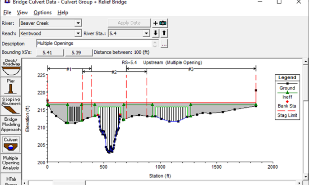
Take the following example, in the figure below.

First of all, I always like to open up the bridge plot along side its htab plot (make sure the vertical axis is consistent) so that I can graphically explain any discontinuities in the htab curves. This example shows a significant discontinuity at around 10,000 cfs (you can click on the figure above to get a better view). It’s very obvious from looking at the plot that this is the range at which the flow transitions from low flow to pressure flow and then on to pressure and weir flow. Also, notice that the ineffective flow triggers turn off in this range. It appears that the creater of this model tried to lessen the impact of the ineffective flow areas instantaneously turning effective by significantly raising up the n-values in the overbank. Not a bad technique, but obviously didn’t completely solve the problem.
Things you can tweak that may provide more sensible results and a better set of Htab curves are:
-Coefficients (bridge and culvert coefficients).
-Ineffective flow areas upstream and downstream of the crossing.
-Bridge modeling approach.
-Placement of cross sections. Sometimes if they are too far from the crossing, or to sparsely spaced leading up to the crossing, it can cause these types of problems.
-Consider modeling a bridge as a culvert, particularly if it has a very deep deck and small relative opening. Likewise, consider modeling a culvert as a bridge, particularly if it has a very large opening, relative to the deck thickness (conspan culverts are good examples).
If the problem is only a very small discrepancy in upstream head levels, a refinement of the computation tolerances might yield better results. For example, let’s say you are trying to provide a “no-rise” condition, and you feel that there should be no rise (i.e. new bridge opening is bigger than old bridge opening with a higher low chord). However, you’re results are showing a 1 to 2 hundreths of a foot of rise for the new bridge. This is most likely numerical issue and a refinement of the computation tolerances might yield better results.
 First of all, I always like to open up the bridge plot along side its htab plot (make sure the vertical axis is consistent) so that I can graphically explain any discontinuities in the htab curves. This example shows a significant discontinuity at around 10,000 cfs (you can click on the figure above to get a better view). It’s very obvious from looking at the plot that this is the range at which the flow transitions from low flow to pressure flow and then on to pressure and weir flow. Also, notice that the ineffective flow triggers turn off in this range. It appears that the creater of this model tried to lessen the impact of the ineffective flow areas instantaneously turning effective by significantly raising up the n-values in the overbank. Not a bad technique, but obviously didn’t completely solve the problem.


Comments
Heyday
on August 4, 2009I have a situation where the wselev jumps up a couple of feet in the culvert cross sections compared to the upstream and downstream cross sections. I have tried changing the modeling approach and all of the other variables I can think of. Any ideas on what would cause this?
Ben
Great blog, by the way.
Chris G.
on August 4, 2009Thanks Ben. I'm assuming that by the culvert cross sections, you are talking about the bounding cross sections (cross sections 2 and 3, in HEC-RAS "lingo"). Usually when I see a jump in wselev in those cross sections, it is due to non-existent, or poorly-defined ineffective flow areas in those cross sections. Make sure you are properly defining the contraction and the expansion to and from the culvert. I've also seen this phenomenon where the cross section spacing is too coarse around the crossing. You might try interpolating some cross sections and see if that helps. Give that a try, if it's still causing problems, let me know.
BenRufenacht
on August 4, 2009Actually, it is the two structure cross sections created by HEC-RAS that have the jumps. Cross sections 2 and 3 look fine. I should mention that the model is a dam breach model, so it is unsteady, with a very steep hydrograph.
Chris G.
on August 4, 2009Sorry…my bad. But, I think my comment on the ineffective flow areas still applies, especially now for an unsteady flow model. Imagine a full flowing channel that has to squeeze through a culvert. It needs some distance for that water to contract. This needs to be modeled with ineffective flow areas. However, since it is an unsteady flow model, check the Htab parameters for your culvert first (its easy to do). Try to refine the parameters as much as possible. I'll usually try 80/60/40 for my number of points/curves. Also, provide a max elevation and max flow. This will help to refine the family of curves that RAS uses at this culvert during the computations. If these curves are too coarse, you can get weird results at bridges and culverts. Let me know how it goes. You can always send me a screen shot if you think that might help.
Andy
on September 8, 2010You had mentioned that the equations for modeling bridges and culverts are quite different. Does the "Bridge Modeling Approach" (i.e. high and low flow methods) apply to culverts as well?
Chris G.
on September 8, 2010Not for low flow conditions. HEC-RAS will use the inlet or outlet culvert equations for low flow conditions. If the upstream energy surpasses the minimum weir flow elevation, RAS will use the weir flow equation along with the culvert equations (and balance the energies at the upstream end) if the high flow method "pressure and weir" is selected. If the energy method is selected for high flow conditions, I think RAS will still use the weir equation with the culvert equations, but I'm not sure about that. You can easily check that if you have a data set with an overtopping culvert. Just check the culvert detailed output table and see if it lists weir flow.
kyle macdonald
on December 5, 2012I have run in to a problem with my interface with Arc GIS, Hec Geo Ras and Hec Ras. I was hoping that you all may shed some light on the subject or refer me to someone that could help. I have be getting conflicting measurements from GIS into Hec Ras. I would measure two cross-section that are constraining a Bridge or Dam in Arch GIS and then compare this to the measurement give to me in HecRas between two of the same xsection. The measurements are much different from one another. I have check and recheck units and my projection NAD_1983_UTM_Zone_19N, That includes all layer that are required for HecGeo Ras, and my TIN. My elevation data is NED Elevation raster data if that helps. The only different projection on the GIS map is the base map that is in GCS_WGS_1984 that should not change anything. Please let me know if you think you can help out with this problem with some helpful hits and troubleshooting Ideas.
Chris G.
on December 7, 2012Hard to say. Are your cross sections skewed in RAS? Could that be the discrepancy? You may want to stip everything down to only the affected cross sections and try to bring them in "isolated". That sometimes helps to identify the problem. Good luck.
Anonymous
on April 29, 2013I am modeling a channel that is turning an 18'x10' bridge into a 28'x10' bridge without raising the road profile. The upstream WSEL for every return event is lower for the longer bridge except for the 500-year. One thing I noticed is that although the WSEL exceeds the elevation of the roadway, HEC-RAS is not picking up any weir flow over the road. I'd appreciate any help in troubleshooting!
Chris G.
on May 1, 2013Not sure. Weir flow is based on the energy level in the cross section just upstream of the bridge (section 3). Double check that it is indeed higher than the bridge deck and that the water above the bridge is NOT ineffective. Otherwise, I'm scratching my head…
Anonymous
on September 4, 2013I am modelling a short section of a small river including a bridge without a pier. Here I came across two problems:
– by turning on the pressure and weir flow mode (brige modeling approach) the water levels for low flow did change, resulting in a feet higher than modeling with the normal approach (energy only). I thought, switching on the pressure and weir flow mode influences only the high flows?
– curiosly the high cord of the brigde has an influence on the water level when calculating "high" low flows (nearly high flow flows) with the modeling aproach energy only. I experienced the following thing: if the height of the bridge (high cord- low chord) is less than approx 3 feet and the water level of the calcuting profile (at the upstream cross section of the bridge) is less than 1/4 lower than the low chord of the bridge at the upstream cross section, then the water level jumps at this cross section (about 1/4 feet). As an effect the water level is higher at this cross section as well as one upstream.
I know, it s a bit confusing, but maybe you can help me. Is it only a numerical problem? Thanks for the blog too.
Chris G.
on September 4, 2013Hi Anonymous-
The problem you are experiences stems from how HEC-RAS measures the head level upstream of the bridge. By default, HEC-RAS uses the energy grade line as it's reference for the upstream head. Under most conditions, this is fine, and in fact is the correct way to properly account for both potential and kinetic energy upstream of the bridge. However, when the water surface elevation is close to the lower chord of the bridge deck, you may find that the energy level is actually higher than the lower chord, in which case RAS assumes pressure flow (high flow condition), even though the water surface elevation would lead you to believe it is still a low flow condition. This also happens in very fast moving water, where the velocity head can be quite high (again pushing the energy grade elevation above the low chord).
To fix this, you can go to the Options menu item in the bridge editor and select "Pressure Flow Criteria". Then select the option for "Upstream water surface".
Also, the same thing can happen when you are near the transition from pressure flow to pressure and weir flow (RAS uses the energy elevation to determine when it switches from pressure flow to pressure and weir flow). In that case, you can increase the minimu weir flow elevation in the Deck/Roadway editor to take care of that problem.
Hope this helps. Good luck!
Ali
on October 10, 2013I have a stupid question, but I am confused about defining the cross sections upstream and downstream of a bridge or culvert. The manual says there should be four cross sections: two upstream (one immediately, and the other further). Same for the DS. But after I define the culvert and run the steady flow, Hec Ras makes two cross sections of "Culv U" and "Culv D". Are these cross sections those that the manual refers to as cross sections immediately US and DS? In other words, is it correct to just define a cross section further upstream and a cross section further downstream of a culvert?
Thank you!
Chris G.
on October 11, 2013You are correct in defining 4 cross sections. HEC-RAS will then automatically create 2 additional cross sections which represent the geometry just inside the bridge or culvert. These are Culv U and Culv D (or Bridge U and Bridge D, if you have a bridge), NOT the cross sections immediately US and DS. They combine a copy of the bounding cross sections you entered and the embankment geometry.
Ali
on October 11, 2013Excellent! Thank you Chris for the prompt response. It was really helpful. I have another question. We have always read and talked that these cross sections should be immediately US or DS of the bridge face. I know they should not be very close (let's say 1 ft), and not very far from the bridge. But is there a way to determine the distance of these four cross sections as a function of bridgeculvert size, or in terms of stream dimension?
Chris G.
on October 15, 2013Yes, there is guidance in Appendix B of the HEC-RAS Hydraulic Reference Manual.
Ali
on October 15, 2013Found it there. Thanks!
Anonymous
on January 10, 2014Chris,
I am currently reviewing a HEC-RAS model to verify accurate results for the current site conditions, we will then use the model for a new proposed dam that meets no rise criteria.
My question is, the consultant that did the model did use ineffective flow areas for the bridges and I have verified that they are indeed correct (or at least close enough for my comfort). However, at the location of the current dam they also included ineffective flow areas. I am wondering do the same rules for placing XS 4,3,2 and 1 apply to dams as they do to culverts and bridges? I am asking because they included cross-sections immediately upstream of cross section 3 (less than 10 feet away actually), but they do not include any ineffective flow areas here. If you could point me in the right direction on how to use IF areas with dams that would be great!
We are running 100yr steady flow events for verification.
Thanks.
Chris G.
on January 10, 2014Yes, you use the exact same cross section layout. The only difference is that instead of contracting flow to go through a bridge opening or culvert, you're squeezing it through gates, or low level outlets, or spillways, turbine units, etc. If you have multiple outlet locations, you may need to use multiple blocked ineffective flow areas. Any cross sections placed between XS3 and XS4 (the contraction reach) should have ineffective flow areas defined. Same thing for any cross sections placed between XS1 and XS2 (the expansion reach). Also, make sure you have your ineffective flow trigger elevations set so that they turn off once the ineffective flow is activated (i.e.spilling over an emergency spillway, or overtopping a dam). Good luck! @RASModel
Anonymous
on January 13, 2014Perfect, just wanted to verify, Thanks!
Anonymous
on February 11, 2014I have a single span bridge model with one WS profile (500 yr) that overtops the roadway and all the other profiles are passed through. I am concerned about my surface profiles crossing each other starting at the upstream face of the bridge. The 500 yr WS profile, which overtops the roadway, drops below my 100 & 50 yr profiles for a few sections upstream before it rises back above the 100 & 50 further upstream. Is this normal and due to the weir flow of the overtopping condition? I have the normal ineffective area cones (1.0 & 2.0) and 0.3/0.5 for expansion and contraction coefficients. Should the profiles ever cross? Thanks in advance.
Chris G.
on February 11, 2014In general, they should not cross. Try using energy equation for high flow, and/or adjusting your bridge loss and discharge coefficients until the results are reasonable. Adjustment of your ineffective flow triggers (both spatial location and on/off elevation) may help. Also, make sure you have enough cross sections. If they are spaced too far apart, you can get weird results like profiles crossing.
Good Luck-
@RASModel
Anonymous
on February 11, 2014Thanks for the quick reply Chris. I was already using the energy equation for high flow, but I'm not entirely sure where you adjust bridge loss and discharge coefficients. Is this for a different bridge modeling approach. An interesting side note is that my profiles stopped crossing after I changed the bounding bridge cross section contraction and expansion ratios to 0.1 and 0.3. Is it correct to have lower contraction and expansion coefficients at the structure and different coefficients outside the bridge sections within the cone of influence, etc. I have 0.1/0.3 for bridge sections, 0.3/0.5 outside bridge and within cones of influence, 0.1/0.3 outside bridge and outside cones of influence. The other confusing parameter to set is the elevations of the ineffective flow areas. How is this typically done on models that have potential overtopping or upstream WS elevations that are higher than the crown elevation of the roadway? What are these elevations set at within the bridge and outside the bridge? Thanks!
Jennifer Zung
on February 17, 2014I am modeling a proposed bridge and are considering two options, one is a steel bridge with vertical concrete abutments and the other is a concrete box culvert. I am getting a very large difference between the modeling results of the bridge vs. the culvert, even though they are basically identical structures. Using bridge modeling the resulting 50-yr wsel is about 5' higher than the culvert model results and it is overtopping the road. The culvert model shows the 50-yr flow passing through the culvert with about 2' of freeboard to the "low chord" of the culvert. What is the explanation for this large difference? I assume it has to do with the different modeling techniques but would expect the results to be closer than they are.
Chris G.
on February 28, 2014Typically, you want your contraction and expansion coefficients to be higher at bridges for cross sections 2, 3, and 4. However, these are somewhat subjective parameters, and if you can justify it, AND it produces logical results, then go with what works. The bridge coefficients are located in the bridge modeling approach (pier coefficients, high flow coefficients), in the deck editor (weir coefficient), and the contraction/expansion coefficients (XS editor). The elevations where ineffective flow triggers turn on/off is also subjective. Generally speaking, I'll set mine to turn off on the upstream side when the w/s elevation slightly exceeds the bridge deck elevation. On the downstream side, I usually set them slightly below the bridge deck elevation to account for the ws drawdown over the deck. This frequently requires some trial and error to make sure both upstream and downstream triggers turn off/on at the same time (or same profile).
Chris G.
on February 28, 2014You are exactly right-the difference is that bridges use bridge equations, culverts use culvert equations. the results, especially around transition areas (low flow to pressure flow, pressure flow to weir flow) can be quite dramatic. I will usually adjust the bridge and/or culvert coefficients until the answers make more sense. Sometimes one or the other (bridge or culvert routines) are just more applicable than the other, in which case you may not be able to get one to give realistic answers. For example, trying to model a realitively small opening with a large deck can give weird results if trying to model with the bridge routines. In that case, the culvert routines are more appropriate, and trying to get similar results between modeling as a bridge and as a culvert would be a futile (and unessesary) effort.
Anonymous
on May 8, 2014I have a question for modeling bridge. I have two bridges they are very close, but I have to modeling them as two bridges since their geomtries are so different. they are almost parallel. How can I put the bouding cross sections between two bridges? Can I use put only one cross section between two bridges for both bridges' bounding cross sections?
Chris G.
on May 11, 2014You could try to squeeze two cross sections between them with very small reach lengths, or pick which of the two bridges will control flows and just use that. You may consider taking the most restrictive aspects of each and combine them into one hybrid bridge. The key for modeling parallel bridges is to understand how flow patterns will behave through (and over/around) the bridges and set up your geometry to capture that. You may need multiple geometries to simulate a full range of flows. Great question! Good luck.
Fatema Begum
on July 2, 2014I have a HECRAS model for simple span bridge without pier. For very high flow my immediate upstream section of the bridge shows around 5 ft higher WS than the bridge section WS and it is a weir flow. Also the WS is much higher than the high chord of the bridge, which does not look write to me. The bridge geometry has been chagned for the bridge. Can you also discuss how the ineffective area has to be defined for bridge with wing wall.
Chris G.
on July 2, 2014I think you are on the right track, thinking about ineffective flow areas to help solve your problem. However, the wing wall should not really affect the placement of your ineffective flow area. The wing walls should be inside of cross sections 2 and 3 (4 cross section bridge layout). Cross Sections 2 and 3 should have ineffective flow areas to properly define the wedge of relatively stagnate water adjacent to the embankments and away from the bridge opening.
Fatema Begum
on July 2, 2014Thanks a lot. I was wondering how to play with the ineffective area. I put 1:1 in upstream cross section and 3:1 in downstream cross section. Upstream height upto bridge elevation and downstream height half height down of bridge thickness. What you think I should change to abrupt change in this immediate upstream section higher elevation than the bridge high elevation. How can I send you the photo of profile, if you can see if it looks correct. If correct than why? The immediate upstream section water elevation is 2 ft higher than the bridge top elevation. IT looks like backwater flow. But if it is backwater flow, why the immediate upstream water is 2 ft higher than the bridge high elevation.
Chris G.
on July 2, 2014Send me a debug report zip file of your model data files (go to this link if you don't know how to do that). http://hecrasmodel.blogspot.com/2008/12/hec-ras-debug-report.html
Tell me which bridge it is and I'll take a quick look to see if I can figure it out.
cgoodell@westconsultants.com
Anonymous
on January 29, 2015Chris,
Thank you for the post. I am currently experiencing an inconsistency with my model results and was hoping you may have be able to provide some insight.
In my Profile Output Table – Bridge Only, I have a Q Weir of just under 2.4% of Q Total. However, when I review my the W.S. Elev at my Upstream Full Valley cross section (3 ft. upstream of upstream face of bridge), it is lower than my minimum roadway elevation as entered in the Deck/Roadway Data Editor. How can I have over-the-road flow (>0 Q Weir) if the W.S. Elev is lower than the minimum roadway elevation?
Thanks!
Chris Goodell
on February 1, 2015Hi Anonymous-
RAS computes weir flow based on the energy elevation, not water surface elevation. Just set your minimum weir flow elevation slightly above the computed energy elevation and rerun your model. That should solve your problem. Good luck!
Chris
Jeremy Payne
on March 26, 2015Hi Chris,
I've encountered a tricky situation. I'm modeling a culvert and have set it up with the 4 prescribed cross sections from the manual. When I run the model, the 10-yr profile jumps above the 50 and 100 year profiles for RAS cross sections 1, 2, and 3. I tried changing the expansion/contraction coefficients, the solution criteria for the culvert, and the pressure flow criteria. When I look at the output for the culvert, it shows a drastic decrease in conveyance through the culvert for the 10-year event, but appears to be normal for the other profiles. I don't know why the model only decreases the conveyance for that one particular storm event. Any ideas would be helpful.
Thanks so much,
Jeremy
Chris Goodell
on March 27, 2015It's hard to say without the benefit of seeing your model. I would first check to see what is different in the 4 bounding cross sections at the different profiles. Are there ineffective flows for the 10 year, but not the others? If so, could the placement of these be affecting the profile by that much? It could just a numerical error. Are you defaulting to critical depth anywhere for the 10-yr profile? That can frequently cause an unrealistically high stage just upstream.
Anonymous
on April 24, 2015Hi Chris, I am trying to run scour calcs for a bridge using HEC-RAS steady flow regime. I find that the Hydraulic Design editor is not populating the data for the left and right overbank sections from the steady flow output file as it normally does. Do you have any suggestions?
Chris Goodell
on May 5, 2015Do you have any flow in the overbanks? The scour calcs in HEC-RAS have been know to have some bugs, particularly in SI units, but I usually see this when I have no flow in the overbanks.
SamihaT
on May 22, 2015Hi Chris,
I am new to HEC-RAS. I have a simply question. The bridge I am trying to model has 5 piers, each around 9 m placed 126 m apart along the X section. If there NO abutment along the river X-section (no significant flow obstruct along the floodplain) how should I define ineffective areas for X-section 2 and 3 just upstream and downstream of the bridge?
Chris Goodell
on May 22, 2015If there is no obstruction to flow from abutments, then you could do without the ineffective flow areas (they are not required at bridges). The thing to consider is "does my bridge create significant inundated areas that do not actively flow in the downstream direction." If yes, do your best to identify those areas and mark them with ineffective flow areas. If not, just forego the ineffective flow areas at this bridge.
Sara
on June 11, 2015Hi. Thank you for sharing this useful information. I have a question. I had done a river modeling by hec ras, there was 13 bridges all over the domain. But now I want to remove 3 bridges andcompare the results. I wanna know is it ok just to delete the cross section information of up and downstream of the project or I should do something else?
Chris G.
on June 11, 2015You should leave the bounding cross sections when you delete the bridge(s). Also, remove any ineffective flow triggers that were set to account for the contraction and expansion through the bridge.
Anonymous
on July 2, 2015Good day. Just want to inquire about adding a bridge to an existing HEC file.
After adding the bridge station, a window pops out. "Warning. There needs to be cross sections on the upstream and downstream of all interior boundary structures (Bridge, Culverts, Inline Weirs). The BR at RS: [Bridge Station] does not have a XS on both sides." What does it means? How can it be solved?
Chris Goodell
on July 3, 2015XS stands for cross section. You need to have at least 2 cross sections upstream of a bridge and at least 2 cross sections downstream of a bridge.
Anonymous
on July 5, 2015Already tried using interpolated sections near the [Bridge Station] and producing bridge's centerline and edges with the GIS file, still yielding the same warning. The geometric data used was exported from Civil 3D. Did I miss some steps along the way? What can be done?
Truly Thanks
Chris Goodell
on July 6, 2015Not sure. Check your Node Name Table (geometry editor, Tables…Names…Node Names). Look for the river station with your bridge (should have a BR at the end of the number). Then make sure you have at least 2 cross sections above it and 2 below it in the table. If not, then cross sections are not being imported properly. If you only have one (or less) cross sections on either side of the bridge, then interpolation will not help you. You must import cross sections.
Anonymous
on July 7, 2015Hi. I need some help with Culvert design. I am new to HECRAS (4.1.0 version). I have a culvert length of 400ft and the road width of 100 ft. I have U/S and D/S cross sections cut at 10ft from the face of the road. When I enter 100ft in roadway width and 400ft in ;ength of culvert, the program is giving an error message. The example shows roadway width of 40ft and section spacing of 10ft and length of culvert as 60ft (10+40+10). Please help.
Alos, how do I consider high headwalls for a shortened culvert lengthscenario?
Chris Goodell
on July 7, 2015Your bounding cross sections must be outside the culvert. They should be a minimum of 400 ft apart. Headwalls are accounted for in the entrance loss coefficient. The tables should give you a good idea of what coefficient to use.
Anonymous
on July 7, 2015Thank you! okay I space the cross sections atleast 400ft which means the "width" in the deck/roadway editor should be adjusted accordingly, isn't it? As I mentioned, if the roadway width was entered 100ft then the program was giving an error message.
Chris Goodell
on July 7, 2015Not necessarily. You can have the bounding cross sections spaced 400 ft and still have a road width of 100 ft. That just means there is a 150 ft space between the top of the structure and the next cross section upstream (or downstream). Keep in mind, the culvert can be longer than the roadway width (and frequently is). But it cannot be longer than the span between the bounding cross sections.
Anonymous
on July 7, 2015Hello. I'm just new to HECRAS, browsing the bridge examples included in the program. Just wondering, the cross section created run from right to left? Is that the basis of analysis used by HECRAS? Thanks
Chris Goodell
on July 9, 2015From left to right, looking in the downstream direction.
Anonymous
on July 10, 2015Hi!
I am designing a variety of culverts in HECRAS and I also use Ras mapper. I use culvert designs (usually circular or pipe arch). I use levees and ineffective areas. Ineffective areas on cross section 2 and 3 have flow triggers = top chord. On cross sections that are up to 5 meters downstream (ie. considered being within the expansion reach) I set ineffective areas slightly wider and have flow triggers = top chord. On cross sections that are up to 5 meters upstream (ie. considered being within the contraction reach), I set ineffective areas slightly wider and have flow triggers slightly higher than top chord. On the cross section just downstream the culvert I also use lid with low EI. = top of culvert and high EI. = top chord.
Question 1: In HECRAS I have Q50 and Q200 and they are crossing just upstream of several culverts. I get warnings such as “the energy equation could not be balanced within the specified number of iterations and that the program used critical depth for the water surface and continued with the calculations” and “During the standard step iterations, where the assumed water surface was set equal to critical depth, the calculated water surface came back below critical depth. This indicates that there is not a valid subcritical answer. The program defaulted to critical depth. Any recommendations on how to solve this problem?
Question 2: In Ras mapper it seems as if the program don't use the water height within the culvert. Instead, it interpolates the water height from the cross section just upstream to downstream. As a result the deck is only partially flooded in RAS mapper despite showing flooding in HECRAS. Is this a bug or is there an explanation to this?
Chris Goodell
on July 10, 2015Question 1: It's very common that when your solution defaults to critical depth in one profile, it temporarily criss-crosses with another profile. When defaulting to critical depth, it's usually either a sudden contraction that is not properly defined, or not enough cross sections. You could try interpolating a few more cross sections around the cross section that is defaulting to critical depth, or try smoothing out the expansion and contraction reaches with your ineffective flow triggers. Also, check the consistency of flow distribution between your 3 sub sections (lob, ch, rob) upstream and downstream of your culvert structure. If you have roughly 20%, 70%, and 10% in your lob, ch, and rob respectively, then you should have about the same percentages in each downstream of the culvert. Proper ineffective flow trigger locations and elevations can fix this. And sometimes it requires you to have your ineffective trigger elevations slightly higher than the high chord on the upstream end and/or slightly lower than the high chord on the downstream end.
Question 2: That is likely the case. I wouldn't necessarily call it a bug. It's just how HEC decided to map culverts in RAS Mapper. Probably because the terrain doesn't include the inside of the culvert, and culverts in RAS have no geospatial coordinates, so there's no way to know how to map it.
Good luck!
Anonymous
on July 13, 2015Hi
I am trying to model an existing bridge in HEC-RAS by replacing the existing structure with a proposed culvert. The water surface elevations immediately downstream of the proposed culvert are coming out to be higher than existing conditions, even though the culvert has larger opening area than the existing bridge. Any idea why I am getting the results with higher water surface elevations downstream of the structure?
Chris Goodell
on July 13, 2015If you have increased the flow area downstream of the bridge (not culvert), the water surface elevation should go up, with a corresponding decrease in the velocity head. This is a common occurrence when pushing out the ineffective flow areas to simulate a bigger opening.
Anonymous
on July 15, 2015Thanks for your reply Chris. The proposed opening width has not changed much, it's the depth/rise that's increased but the overall increase is not that significant as there are not many changes happening along the roadway. I kept the ineffective flow areas the same but even then I am getting the increase in downstream water surface elevations (with a big hydraulic jump within the culvert itself). Is this common?
Anonymous
on July 15, 2015Hello. I am designing a proposed bridge above a river, Just asking if there will be some factors to be considered in bridge modelling if the river runs directly under the proposed bridge?
Also, what will be the consideration if the said proposed bridge intersects a snake-like river?
Thanks
Anonymous
on July 24, 2015Hi Chris
I am modeling an existing bridge & the stream has a dam around 500 feet upstream of the bridge crossing. I have included the dam cross-sections as part of my analysis right now but the 10-year water surface elevation increases whereas all the other water surface profiles get lowered (even the 500-year) just downstream of the bridge. Not sure why this occurs. I am going to model the dam as an inline structure as well to see if it makes any difference.
Thanks.
Anonymous
on July 27, 2015Hi
I am trying to model a systems of short box culverts (length of ard 40m). At both upstream and downstream of the culverts are long closed drains (~400m). In my HEC-RAS model, the closed drains are described using lid function. Somehow the results show the simulated water level as even higher than the lid's lower boundary. The culvert flows full. Do you know what might have gone wrong with the model?
Thanks!
Chris Goodell
on July 31, 2015Not sure I would say it's common, but not unusual either. I think as long as your energy grade line isn't doing anything weird, it's probably okay.
Chris Goodell
on July 31, 2015Why do you think the culverts flowing full is wrong?
Anonymous
on August 5, 2015Hello
I am modeling a river where the flow splits around a bridge during the 100-year storm event. The road basically comes to a T after the bridge and runs parallel to the stream. I originally modeled the road as a lateral weir which allowed flows to exit the main reach upstream of the bridge and reenter into the main reach downstream of the bridge. By doing this I was able to match the rating curve from the gage on the downstream end of the bridge. However the upstream water surfaces are showing some incongruities. The road is significantly overtopped and yet there is a substantial difference (3+ feet) between the WSE of the main reach and the tributary. I then removed the lateral weir and created a split upstream of the bridge. This still is showing varying water surfaces between the main reach and tributary. Any suggestions how best to model this? I am using flow optimization. Should I manually split the flow? Any suggestions would be so appreciated.
Thanks
Anonymous
on August 6, 2015Hi Chris
I have a box culvert I modeled in a stream where at the culvert outlet the flow empties into the ohio river so I only have one cross section downstream, My problem is this, my bridge scour is not populated with ANY info after running successful steady flow analysis
Chris Goodell
on August 6, 2015Strange that it would run with only one cross section downstream of the culvert. Perhaps adding another cross section will get you scour to populate.
Chris Goodell
on August 10, 2015I like your first approach. I think you may have better luck running in unsteady flow. You can still use a constant discharge for steady state conditions. It's just that when using lateral structures for flow splits like that, unsteady works much better.
Christine
on September 28, 2015Hi Chris,
Maybe you can help me with this problem with my bridges. RAS has calculated a set of curves for one of my bridges, but when I run the model, I can see in the Stage and Flow Hydrographs output that the model is using flow/stage ordinates that are below my free flow curve. Any idea why this is happening?
Thank you,
Christine
Chris Goodell
on September 29, 2015Christine-
That doesn't sound correct. I'm not sure how that could happen. Let me know if you figure it out.
Yari
on September 29, 2015Hello Chris good afternoon.
I have a case where I am inserting the structure of a bridge, but on either side of it; at the entrances. I have 7 culverts of different sizes and I can not define exactly what the ineffective areas. What it is done in these cases? I hope you can help me.
Yari, Mexico.
Chris Goodell
on September 29, 2015Hi Yari-
Most people put their ineffective flow triggers just outside the outer-most culvert.
Chris
Anonymous
on October 6, 2015Hey!
I am modelling a bridge in Hecras, which is situated at the coast. The river is entering the sea before the bridge crossing. I get a warning which says the following:
" The momentum, class B, supercritical, water surface downstream of the bridge had a higher energy than the upstream cross section. This is not physically possible. The downstream water surface has been computed by taking the momentum result inside of the bridge and performing an energy balance. "
Do you know what is likely to be the consequence of this behavour (what I should change in order to make the computations work normally?
Kind regards
Chris Goodell
on October 6, 2015It just means RAS is not able to compute with the momentum equation. In this case, I'll usually accept its workaround, or just switch to the energy method. In my experience this happens with high or significant backwater (e.g. tidal), where the energy method may be a better option anyway.
LLCR
on November 3, 2015Hi Chris,
I am performing a HEC-RAS analysis for a culvert replacement project; an existing CM pipe arch (9.5' wide) is to be replaced with a 12' Conspan arch. This is in the southern NJ coastal plain, with very gradual slopes.
The reviewing regulator has indicated that WSE's at the upstream boundary must converge for existing and proposed conditions – or at least be within 0.04 feet (!) – for the full range of conditions modeled. I can't seem to accomplish this without making my proposed hydraulic opening smaller than the existing, which is against the regulations.
Do you have any suggestions? I have adjusted ineffective flow areas, Manning's n values, bridge modeling approach, etc. without any luck. I added a cross section almost three miles upstream and am still not getting convergence for certain storm events. The biggest discrepancy I have is for the 100-year storm (0.61 feet), for which the existing condition overtops and the proposed does not.
Maybe I haven't made the right combination of adjustments? Could there be a situation in which existing/proposed WSE's would not converge almost three miles upstream of the bridge?
Thanks.
Chris Goodell
on November 3, 2015When you say the profiles are not converging, do you mean the proposed profile is lower than the existing/ If so, that should not be a problem with the regulator. In a very shallow system, the backwater effects can last for many miles.
MelR
on November 19, 2015Hi Chris,
Do the bounding cross sections for a bridge/culvert need to have the same starting stationing as the deck/roadway? (ie – same distance from stream centerline)
Chris Goodell
on November 23, 2015No, but it makes it easier to set up your bridge it you do.
Unknown
on January 12, 2016I am performing HEC-RAS analysis of existing culvert. The culvert is consisting of two sections (box Culvert and twin pipes). Between pipes and box culvert there is a inlet structure. How do I enter the geometry data in to Model
KS
on January 12, 2016Hi Chris
I am performing HEC-RAS analysis of existing culvert. The culvert is consisting of two sections (box Culvert and twin pipes). Between pipes and box culvert there is a inlet structure. How do I enter the geometry data in to Model
Chris Goodell
on January 12, 2016You'll have to break the culvert up into two different culverts in RAS, with at least 2 cross sections in between. The "in between" cross sections will have the inlet structure geometry, probably modeled as either a lateral structure or using a lateral inflow (unsteady flow)/flow change location (steady flow). Alternatively, you could model the whole thing as cross sections with lids.
Chris Goodell
on February 12, 2016It depends on what kind of inlet structure you have. you have the option of using one of the culvert types in RAS, you can use a weir, or you can just use a rating curve, if you have one.
Anonymous
on February 24, 2016Hello Chris,
Awesome blog! I have a steady state model with multiple bridges along a fairly steep riverbed profile. We are running multiple low flow methods (energy and momentum) and using the highest energy answer since the bridges have piers. In each of the bridge locations, the WSE drops within the bridge (drawdowns), which suggests that we are experiencing Class B low flow and will have a hydraulic jump somewhere downstream of the bridge. Our agency reviewer is suggesting that "drawdowns that occur with a structure may be acceptable if an explanation is provided for why they cannot be removed." We've tried some of the standard tricks of adjusting geometry, Manning's, and entrance/exit coefficients and cannot "remove" the drawdowns. Is there a standard way to confirm that the drawdowns are real and would actually occur under the modeled flow scenarios? I'm also struggling with an explanation other than that we believe the drawdowns are due to Class B low flow. Any light you can shed would be appreciated!
RTW
Chris Goodell
on February 24, 2016Thanks! Are you sure it's Class B? A lowering of the water surface through a bridge opening is completely normal and can happen with Class A flow. The difference is in Class B flow, the flow goes through critical depth to super-critical through the bridge before it jumps back to sub-critical. Class A remains subcritical throughout, even if it displays a drawdown. If it is indeed Class A flow, there is no problem. Water surface will always decrease in a contracted section. This is covered in any open channel flow textbook and the reviewer should be aware of this. If it is Class B flow (dips below critical depth), then the only thing you can do to get rid of it (assuming it is not there for the "no-bridge" alternative) is to lessen the contraction. In other words, make the bridge opening bigger and smooth out your ineffective flows in both the contraction and expansion reach. If any of your cross sections "default" to critical depth, that means there was an error with the computations and you need to fix that before you can use the results from the model.
Good luck!
Samantha
on February 26, 2016Hi Chris,
I'm having some issues with a very skewed bridge. I have already skewed the bridge 45 degrees. Due to the skew the us and ds cross sections are far away from the bridge because if they were any closer they would cross over the skewed bridge, so adding ineffective flow areas isn't really a solution. I'm using unsteady flow with a relatively low slope (0.008). The problem I am having is that the water surface bulges significantly underneath the bridge. The geometry is a consistent width and shape from approach to exit so there isn't any contraction that would explain the bulging. I have toyed around with different contraction values but it doesn't really make a difference. Any ideas/tips/tricks? thanks!
Chris Goodell
on February 26, 2016The upstream and downstream cross sections that bound the bridge should be parallel to the bridge. Then you skew those cross sections as well as the bridge. Hope that helps.
Anonymous
on March 3, 2016Hello! Congrats for the super helpful blog… I have to estimate scour for a new bridge with 3 openings on a wide floodway with 2 extra relief culverts. Just upstream there is an old bridge with openings that cover the whole floodway (therefore scour depth is an important issue) . The new openings and culverts align with (some of) the upstream openings. Hec Ras does not calculate scour for multiple openings. How would you go around this??
Thank, you!
Katia
Chris Goodell
on March 3, 2016Thanks Katia! I would recommend running it as a multiple opening in RAS, but then compute scour external to RAS. I usually do scour on a spreadsheet. The bridge scour routines in RAS are outdated and a little bit confusing to use properly. Get ahold of the HEC-18 document from Federal Highways for the latest methods for computing scour.
Jj
on March 6, 2016Hi Chris. I'm having an issue with my hec-ras model upstream of my culvert. I have 3 cross-sections defined upstream. And when I run the smaller storms-1&2-yr events, the water surface elevation goes below my ground surface elevation at each alternate section. I know that's a mistake … But not sure what could be causing this error. Any thoughts?
Jj
on March 6, 2016This comment has been removed by a blog administrator.
Chris Goodell
on March 7, 2016If unsteady, sounds like your model might be unstable.
Anonymous
on March 14, 2016Hi Chris,
I have a follow-up to this. Is it normal for the model to display a drawdown in open channel portions that have sudden expansions/contractions in floodplain area? I have a 500-year flood run that shows a drawdown in a cross-section where the HGL is completely contained within the river channel just upstream of a cross-section where the HGL expands into an open floodplain. The model is not defaulting to critical depth, and the EGL is smooth and believable through the transition. The model seems to perform similarly for the 100-year flood run as well, only the drawdown is less pronounced/noticeable.
Thanks for any comment you can provide!
-Steve
Chris Goodell
on March 14, 2016Steve-
Yes, that is quite normal. Where a cross section is constricted relative to its neighboring cross sections, you should expect a decrease in water surface elevation (sometimes very slight). Most hydraulics/open channel flow text books discuss this phenomenon. This is common underneath a bridge constriction, for example. As long as your energy grade line is smooth, and not increasing in the downstream direction, you probably have a good solution.
Ryne Phillips
on March 24, 2016Hey Chris. I'm new to HEC-RAS 5.0's 2D capabilities. I have been able to set up a small model as a test case for a stream bank stabilization project I'm working on. There is only one problem. My flows are going from downstream to upstream rather than upstream to downstream. How is the flow direction set when running a 2-D model only?
Ryne Phillips
on March 24, 2016Hey Chris. I'm relatively new to the 2-D modeling capabilities of HEC-RAS 5.0. I've set up and successfully run a 2-D only model for a stream bank stabilization project I'm currently working on. There is one minor problem…the flow runs from downstream to upstream rather than upstream to downstream. How does the 2-D only component determine the flow direction?
Chris Goodell
on March 28, 2016Hi Ryne-
Flow direction is determined in a 2D area strictly from higher energy to lower energy. Typically, if you place an inflow hydrograph on a 2D area boundary, there will be higher energy there, so the flow will be driven in that direction. However, if you have a tidal downstream boundary, or some other boundary inputs, that can affect the flow direction. For a simple case, if you put a flow hydrograph boundary condition on the upstream end and a normal depth boundary condition on the downstream end, you should see flow generally move from "upstream" to "downstream".
Brittney C
on April 25, 2016Hi Chris, thanks for the great blog! I am running into an issue with modelling the flow through my open bottom culvert (Conspan Arch). The realigned low flow channel runs through the culvert. However, the low flow channel banks partially extend up the culvert sidewalls; thus, rendering blocked flow areas within the culvert. When viewing the cross section output it appears that the model is utilizing the blocked area by the banks as effective flow area.
In attempt to solve this problem, I started playing around with the "Depth Blocked" in the Culvert Data Editor, but this seems to just block the low flow channel out entirely. Is there a way to negate this blocked flow area within the culvert, using any parameter inputs? Or, what would be the best way to model this low flow channel through the culvert?
Thanks Chris!
Brittney
Unknown
on April 26, 2016Hi Chris, thanks for the great blog! I am running into an issue with modelling the flow through my open bottom culvert (Conspan Arch). The realigned low flow channel runs through the culvert. However, the low flow channel banks partially extend up the culvert sidewalls; thus, rendering blocked flow areas within the culvert. When viewing the cross section output it appears that the model is utilizing the blocked area by the banks as effective flow area.
In attempt to solve this problem, I started playing around with the "Depth Blocked" in the Culvert Data Editor, but this seems to just block the low flow channel out entirely. Is there a way to negate this blocked flow area within the culvert, using any parameter inputs? Or, what would be the best way to model this low flow channel through the culvert?
Thanks Chris!
Brittney
Chris Goodell
on April 26, 2016Hi Brittney. I'll give you a couple of options. If you are not too concerned with the results inside the culvert, and just interested in how the culvert itself affects the reach upstream of it, you can use another culvert shape and give it a similar flow area to depth relationship. Just make sure when you adjust the flow area, do so by narrowing or widening the culvert, not by changing it's height (that could have an effect on the transitions between equations). Second option, which would be better if you are interested/concerned with the results inside of the culvert, would be to model the conspan not as a culvert, but as cross sections with lids. Then you could make any shape you want, including yours with the low flow channel inside the culvert.
Good luck!
Anonymous
on May 16, 2016Hi Chris, what would be the possible reasons to have a higher water level corresponding to low flood discharge than to high flood?
Thanks
Anonymous
on May 20, 2016Hi Chris,
I am using RAS (v 3.0.1) for a bridge widening project. We showed no-rise in WSELs between the proposed widening and the pre-project condition. All that is fine. However, I am seeing some increases (max. 0.08 ft) upstream of another structure (culvert) which is almost a mile upstream of our subject bridge. It should be noted that barring the subject bridge there were no changes anywhere else between pre-project and proposed conditions. It is rather perplexing. Is this something common? Would this be an example of inherent inconsistencies with the bridge/culvert routine?
Aj
Chris Goodell
on May 23, 2016That is not common, except for very shallow rivers. I assume this is a steady flow model? If everything is indeed the same between the proposed bridge and the upstream culvert, I can only assume that there is some minor effect. Is the reach very shallow? In very shallow streams/rivers, backwater effects can project upstream for many miles.
Anonymous
on May 24, 2016Chris,
Thank you first of all for taking the time to answer my question.
Yes it is indeed a steady state model that I am working on. As to the channel, I wouldn't consider it to be shallow (it is about 12-16 ft deep in the reach upstream). And for some reason, this is evident only for the more frequent storm event (10-yr) among the events modeled.
Aj
Chris Goodell
on May 25, 2016AJ, my apologies, by shallow I meant in slope, not depth. In other words, a very "flat" river.
Julia Delphia
on June 8, 2016Hi Chris,
I’m modeling a bridge in HEC-RAS 4.1. I have the low flow bridge modeling approach set to compute Energy and Use Highest Energy Answer—none of the other methods are set to compute. The output tables show the Br Sel Method is Momentum. Why would it do that if I didn’t select Momentum to compute? I tried changing to compute Energy and Use Energy, but it still shows the Br Sel Method is Momentum. Any suggestions?
Chris Goodell
on June 8, 2016Check the Summary of errors warnings and notes. Occasionally if RAS has a problem computing with one method, it will automatically switch to another. When it does this it usually tells you about it in the Summary of Error's Warnings and Notes.
Anonymous
on June 12, 2016Hi chris, i'm a newbie on HEC-RAS, i have a question. I've seen many problems on rivers compute by using HEC-RAS, do HEC-RAS can be used to compute flume study just for re-checking, thanks.
Chris Goodell
on June 13, 2016Yes. Certainly!
Anonymous
on June 21, 2016Greetings. I'm starting with HEC-RAS and trying to model a simple culvert. When I select bridge/culvert, no river station is in the list, goes to Options/add a bridge and/or a culvert and select the river station appears the Warning – A node already exists on reach "name reach" at river station "RS number". I've just made the reach and a few cross section, don't know what's happening. Thanks!
Chris Goodell
on June 22, 2016Hi. Did you try a different R.S. number for your culvert? Make sure there are no cross sections with the same R.S. and make sure that you have at least two cross sections upstream and 2 downstream of where you are putting your culvert.
Anonymous
on June 30, 2016Hi Chris, I am somewhat new on HEC-RAS and I've ran into a problem. When modeling an existing dam, I am using an SA/2D connection and I have put in what seems to be the correct information for my parameters. I am able to get my model to run (unsteady model), however the WSEL seems to drop significantly near the outlet… up to 7 feet! Therefore the model is not allowing any flow through the emergency spillway (Which happens in a similar storm in real life). Do you have any idea what is causing this drop in WSEL?
Chris Goodell
on June 30, 2016Sounds like either your model is unstable, or perhaps your SA/2D connection HTAB parameters need refinement. Try providing more resolution to your HTAB parameters for the connection. If that doesn't work, send me your data set and I'll see if I can figure out what's happening.
Unknown
on July 8, 2016Chris, I refined my HTAB parameters for the connection and it did not seem to solve the issue. I am using a full 2D mesh for this design. By using the profile lines tool, I am able to see that the WSE stays fairly consistent until about 150 ft from the SA connection which represents the dam/outlet/emergencyspillway (using culverts and a lowered weir for the spillway). In this 150 feet the WSE gradually drops from an elevation of 1066 to 1060ft. I can't imagine there is that much drawdown from an 18" culvert… The emergency spillway is at 1065 and the WSE is at 1062 at the spillway because of the drawdown. I am thinking the flow is "leaking" through the 2D mesh somehow and drawing down the water. If you were able to imagine any of that from my explanation, if you could please let me know your thoughts on a possible explanation or solution for this issue. Thanks
Chris Goodell
on July 8, 2016That sounds strange. Without seeing your model, I'm not sure I can troubleshoot it. Feel free to email it to me and I'll have a look.
Chris Goodell
on July 8, 2016goodell@westconsultants.com. Chances are its too big to email. You can upload to Google Drive or something similar and send me the link.
Anonymous
on July 13, 2016Hi Chris, Great Blog it has been very useful! I have a project I am working on where we have a culvert that is an existing Stone Arch (semi-circle) atop vertical abutment walls. I can not figure out a way to model this as a culvert because the standard shapes do not adequately represent the openings, is there a way to manually enter a culvert shape or another way to model this scenario? I have run the model as a bridge but the results do not accurately represent the flow conditions expected. The proposed scenario is going to be lining the existing culvert with a material with a little lower manning's "n". The culvert is through an existing railroad embankment that is very tall and causes ponding for the 100-year and 500-year. Do you have any suggestions on how to model this?
Chris Goodell
on July 13, 2016You might try a conspan. Code the vertical abutment walls as part of the geometry of the section, then place the invert of the conspan at the top of those walls. If that doesn't work, you could try modeling it as cross sections with lids. That allows you to code in just about any shape you can think of. However it will only use the energy equation (as with normal cross sections), it will not evaluate inlet/outlet conditions.
Anonymous
on July 13, 2016The conspan approach does not work because the shape is drastically different than the arch that is out there. I had considered the cross sections with lids but we need the inlet and outlet conditions modeled to account for increase efficiency with the entrances and exists. I could try coding the abutments in the sections and placing the arch above it but wouldn't that skew the results since the submergence will only be calculated based on the rise of the arch portion entered at the top and not include the vertical wall portion? I had tried using a box culvert with an arch placed on tope so the bottom of the arch and the top of the box coincided but is seemed like it only split the flow between the two sections but had obtained some wacky results doing that too.
Chris Goodell
on July 13, 2016Not sure about skewing the results. Might be worth trying. If that fails, then I think you're stuck with using the "best fitting" culvert shape. Remember, flow area and rise of the culvert are most important to match. It's better to adjust the width than the rise to match flow area.
Anonymous
on July 15, 2016Hi Chris
I am new on HEC-RAS. I was wondering if you could be able to assist.
I am running an unsteady flow model, problem is that it only computes the geometry processor and it does not compute the unsteady flow simulation and post process. I am getting the following error message:
A change (or known value) in WSEL or EG at a node at river station 100 in reach D caused a WSEL below the bottom of the cross section.
How do I go about solving that problem?
I have viewed the cross section input data but there seems to be no problem with my input data.
Thanks
Chris Goodell
on July 15, 2016My guess is that your flow rate is very low, producing very low depths. This is particularly problematic in steeper streams and/or cross sections with relatively wide and flat channel bottoms. I would suggest either adding in more baseflow to your hydrograph, increasing Manning's n values (if appropriate!), or getting better terrain definition in the main channel. More cross sections in steep reaches can help as well, especially around significant changes in grade. Finally, if all else fails, you can try putting in pilot channels (search the HEC-RAS manual for how to do this).
Unknown
on July 28, 2016Hello Chris! Great blog, very intresting and useful! May I ask you a question about lids in HEC-RAS? I've read in User's manual, chapter 16, that lids can be used to simulate a pressure flow in a close channel. I'm working on a long culvert with variable sections and slope and I've modelled it as a normal set of cross-section with lids on the top. I'm working a steady flow simulation. After running the model, i've noticed that in may section the WS is above the top of the lid. There are also some section with WS IN the lids, between the lower and upper chord! There is an option for lids to allow pression flow likewise bridges (pressure and weir flow mode, in brige modeling approach)ad culverts?
Anonymous
on September 2, 2016Hello Chris! Great blog, very intresting and useful!
I am having a situation where my bridge is located 60' downstream of the dam. What type of analysis (HEC-RAS) do I need to carry out? so far I never came across this situation, please guide me
Chris Goodell
on September 7, 2016It depends on the questions you are trying to answer with HEC-RAS. Bridge scour? No rise analysis? Flood study?
Anonymous
on September 8, 2016no rise analysis
Chris Goodell
on September 8, 2016I'd say a simple steady flow analysis would do. You'll just have to squeeze at least 2 cross sections between the bridge and the dam.
Anonymous
on September 8, 2016The DEP requirement for HEC-RAS is 500' on either side of the bridge.
Chris Goodell
on September 8, 2016Sounds like a conversation with someone at DEP is in order.
Anonymous
on September 20, 2016I have encountered an issue where my high chord bridge elevation in the deck/roadway editor is 86.13 ft, but when I view a run in the profile plot, it displays the high chord at 84.92. All my numbers and file's appear to be correct – nothing obvious is sticking out as a possible reasoning behind this error. Any ideas on what this could be?
Anonymous
on October 5, 2016Hello Chris,
Can a scour analysis be run for a culvert or dam as well as for a bridge?
Chris Goodell
on October 5, 2016Not in HEC-RAS. Typically scour is not an issue since culverts and dams have hard bottoms. Erosion on the other hand…
Jeff Bartz
on October 7, 2016Chris,
We have a model where we are proposing a new 18×8 conspan upstream of an existing 8×11 box culvert. The distance between the culverts is about 60'. We've tried modeling it as one culvert and as two separate ones in series. When modeling as one culvert, we are getting a no rise result. When modeling in series, we are showing a rise of approximately 2 feet upstream. I wouldn't think that the conspan which has a higher capacity than the box culvert would cause such a substantial increase in the WSE but the reviewing agency seems to think that modeling it as one culvert is not acceptable. Any advice/tips you can provide to help?
Chris Goodell
on October 11, 2016Jeff-that's a tricky one. Even with the larger conspan upstream of a smaller box, if the conspan is smaller than the flow area of the stream for the base flood, it will cause a rise (however small or large a rise will generally depend on the velocity head). I think the only way to avoid the rise is to get the conspan out of the active flow area for the base flood. That being said, 2 ft does seem pretty high. Pay close attention to the ineffective flow areas you define upstream and downstream of the conspan. That is usually the cause of excessive rise. Of course, your culvert coefficients will have an effect as well. Good luck-
Chris
Jeff Bartz
on October 11, 2016Chris, Thanks for the response. I think we've resolved the modeling issue. We have reduced the expansion and contraction coefficients between the two culverts and also set the calculation option to be an outlet control condition. We have verified that it is indeed an outlet control condition using the FHWA culvert design equations.
Anonymous
on October 18, 2016Hi Chris, I'm doing a damn break model in HEC-RAS and I have some problem with one of my bridges. I'm working on a little creek with a flow of about 5 m3/s and a break flow of 70 m3/s. When the wave arrived at the bridge, the water level increases a lot (3-4 meters height on 300m large) when all my sections and other bridges have their water level raise by 1m. My HTab Curves looks great, but my rating curve is really different and wrong. Do you know if I can use my HTab Curves in my simulation. Do you have any idea of what I'm doing wrong? I use ineffective flow up/downstream, my HTab Param. are 100-60-50 and head water maximum elevation is 2,5 m higher than the bridge. Thanks for the help
Félix
Chris Goodell
on October 18, 2016Make sure you max out the number of points and number of curves in your Htab parameters. Also make sure that your maximum headwater is just above the maximum level the water will get to. Finally, this is optional, but you can also set a limit on discharge to try to tighten up the curves even more. That being said, sometimes it's just too difficult to model a bridge with a dam breach flood wave. Some people will replace the bridge with a culvert or even an inline structure with a gate to get it to work. Good luck.
Chris
Anonymous
on October 20, 2016I'm modeling a culvert under a road that has weir flow. On the upstream side, almost the entire left overbank is high ground upstream of a small swale/ditch along the road. On the downstream side, the ground is lower than the road in the left overbank. Should the shadow of the upstream high ground limit the available weir length provided by the road itself? If i use cross section 3 for the internal, the weir flow is blocked but i can use section 2 for both internal sections and have the full road as possible weir flow.
Anonymous
on November 2, 2016I am modeling a road crossing of a rectangular concrete channel at a 1% slope. The cross section does not change at the bridge. The flow is super critical so it stays inside the channel and should not touch the low chord of the bridge. RAS is creating a big at the bridge. I can see no reason for this except that RAS appears to use the energy grade rather than the water surface at bridges. With the super critical condition, the energy head is well above the low chord. I have decided to try to model this with out the bridge in place. Your thoughts would be appreciated. I can send the model if you like.
David H
Chris Goodell
on November 3, 2016RAS provides a way to use the water surface elevation rather than energy elevation just of such a case as yours. In the bridge editor, go to Options…Pressure Flow Criteria. Change it to "Upstream water surface". Then rerun and see if that helps.
Anonymous
on November 3, 2016Hello everyone,
I think I might have the same problem here, and it's starting to drive me crazy.
I am modelling a bridge with a culvert (actually 3 bridges with culverts) in a rather steep area (around 5%). I changed pressure flow criteria to "upstream water surface" and the geometry of the channel is converging to the culvert geometry. I still get this very high water surface elevation just right before the culvert, although in the culvert (or downstream) there is supercritical flow with WSE nowhere near the low chord. This only happens when the EL at the upstream culvert xs is higher than the low chord (and yes, I really have selected "upstream water surface;)).
The only clue I found was that this does not happen if I change the calculations from "mixed" flow to "supercritical". So I think what might happen is that HEC-RAS computes a subcritical water depth between the cross section upstream of the culvert and the culvert itself (because they are at the same ground elevation). Could this be the case? And if yes, how do I get rid of it?
Thanks in advance for any suggestions!
Benji
Jason K
on November 30, 2016Hi Chris,
Long-time fan, first time poster.
Do you have any guidance for the selection of the pressure flow criteria? I understand that in most cases the default EGL contact with the low chord is sufficient, but we have a special case where the HGL is well below the low chord, but the EGL is in contact, and so of course there is a big difference in results depending on the pressure flow criteria. The HGL is clear of the soffit, but if the EGL method is used, it induces marginal overtopping.
Conceptually, I suspect the HGL is the more appropriate indicator for the point at which pressure flow should be calculated, but is there a hydraulic / real world premise I am overlooking where the more conservative (EGL) could in fact induce pressure flow, and thus should be taken as our design condition?
Any advice or direction to a reference would be great.
Chris Goodell
on December 5, 2016EGL is used because of the conservative assumption that any disturbance in the flow (debris, etc.) could bring the HGL up to the EGL level. If you have a supercritical reach, or if you suspect that the HGL is so far under the deck that using the EGL is not appropriate, then change the pressure flow criteria. Its really just up to your own judgment.
Anonymous
on December 12, 2016Hello everyone,
I am modeling a combination of culvert with a bridge. The bridge is built above a battery of culvert. i dont know if Hec-Ras allows to model this kind of hydraulic structures?
Thank you.
Anonymous
on February 14, 2017i'm modeling a culvert with a development upstream of it. there is a natural channel in the existing topography that is extremely large-i have calculated its capacity and found it to be able to carry almost 1000 cfs. However, my results are showing that this channel can't every carry 600 cfs. i assume this is due to a backup from the culvert entrance, but i've done some trial and error and enlarged the channel to try and see at what point it could handle my flow, and it seems no matter how much wider/deeper i make it, HEC-RAS just shows the same water surface elevation, and just fills the channel and continues to spill over towards the development. Is this a problem with how i'm modeling it? have you seen this happen in any other circumstances?
Thanks!
Chris Goodell
on February 22, 2017Not sure. Could it maybe be under TW control? That might explain it.
Anonymous
on February 22, 2017Hi,
Here is my issue. WSE is higher at upstream of a culvert, compare to to WSE at downstream, for any large storm events like 50-100-500 yr. However, for 10-yr storm event, it is the other way around; i.e., WSE at the upstream has a drop/smaller and hits the Critical depth. What is that happening and How I would be able to fix it?
Thank you.
Chris Goodell
on February 22, 2017Most likely a better placement of ineffective flow area triggers would solve this problem. Usually that dip to critical depth is because there is too much contraction in the approach.
Anonymous
on March 21, 2017Hi,
I am wondering if anyone has run into a similar situation. I'm modeling a pre- vs post- bridge widening (12' increase) analysis on an old bridge. The existing bridge overtops at Q50, so I raised the low chord of the bridge and lengthened the bridge. In short, my SWE jumped by nearly 2.5' in the post improvement scenario whilst the bridge opening increased by over 100SF. I checked the ineffective areas, post-improvement changes in the ineffective areas only account for a fraction (.3') of the change in SWE. Is it the different modeling approaches: weir for pre- and energy for post- cause the near 2' difference?
Anonymous
on April 12, 2017Is there a way add river wall to hecras? I want to print crosssection with riverwall on each side.
Jennifer Morreale
on April 14, 2017This is the same issue that I am having where we are replacing an 88-ft wide bridge with a 126-ft wide bridge…for the proposed, the WSEL is lower u/s (which makes sense), but the WSEL and EGL are both higher d/s…which didn’t makes sense in terms of continuity alone. So, from what you are saying, is the energy equation causing this increase?…the total energy is constant and so if the velocity head is decreased then the depth needs to increase to maintain the same total energy between sections…??? Is there any way around this type of result? The state DEQ wants mitigation for any increase greater than 0.005’ (and we are getting increases in the 0.03’ range for WSEL and EGL)? How do you even mitigate?
Chris Goodell
on April 18, 2017Jennifer- Assuming you are running a steady state model, your results should be exactly the same up to Cross Section 1 of the bridge (this is the cross section just downstream of the expansion zone). Within the expansion zone downstream of the bridge, I would expect to see a bit of a rise over existing conditions, since the new bridge is wider and there is a fuller conveyance width downstream of the bridge-this results in slower velocities and a resulting slight rise in wsel. This is a real phenomenon and can be described with theoretical equations. A qualified reviewer should recognize this, but you may need to educate them.
Anonymous
on April 20, 2017I'm running existing and proposed models for bridge replacements. However, i keep seeing a decrease from existing to proposed that doesn't make any sense. My existing bridge opening is approx. 72 SF. I started out using a box culvert with a similar opening size, but saw a decrease of nearly a foot at the upstream end of the opening. I started fooling around with different sizes, and still saw a decrease when i took the proposed culvert down to a 2'x2' culvert with a 4SF opening. Obviously there couldn't be a decrease in water surface elevations when the opening goes from 72 SF down to 4 SF, but the models are exactly the same with the same flow rates aside from the bridge/culvert. What could be causing this?
Anonymous
on April 24, 2017Hi Chris.
I am modeling a single span bridge. I have not entered any Encroachments into my model (I double checked that when you go into Steady Flow Analysis –> options –> Encroachments, all the input is blank.)
For some reason the program is creating an encroachment in my model in my upstream bounding cross section. HEC-RAS is setting the encroachment from the left stream bank to the center of my stream at an elevation equal to the 25 year WSE. Do you have any idea why the program is doing this and how I can remove this encroachment that I did not input?
I can only assume that this strange occurrence is the cause of my 25 year WSE dropping below my 10 year WSE within the structure.
So nice of you to create this blog! Thanks
Chris Goodell
on May 1, 2017Thanks for reading! That is a strange one indeed! I've never heard of mysterious encroachments showing up. I wonder if something is stuck in the plan file that isn't showing up in the GUI. You might want to open the plan file in a text editor and see if there is any encroachment data stored there. If so…delete it. Also, this is a long shot, but open up your unsteady flow analysis window and make sure you don't have an encroachment set there (for unsteady flow).
Please report back if you figure it out. Good luck.
Anonymous
on May 3, 2017Hi Chris, first of all thank you for the advices, very useful not only for beginners. I actualy have a doubt in modelling with HEC-RAS a bridge that has a jump below it; I wander if I have to put the jump in the same sections where the bridge is included (I mean XS’s 2 and 3) or if it is better to put it just before (upstream) the bridge. The solutions I’ve obtained can be very different for increasing discharges.
Chris Goodell
on May 3, 2017You're welcome! I'm not sure what you mean by "jump". A hydraulic jump? or a "jump" in the geometry/terrain? In general terms, it's best to put geometric features where they actually are. If under the bridge, put it under the bridge by modifying the internal bridge cross sections. If upstream put it in the upstream cross section.
Anonymous
on May 5, 2017Thank you Chris for the answer, I intended with 'jump' a discontinuity of the bottom (it was a bit ambiguous). Anyway I don't understand how to modify the internal bridge cross sections. Is it possible?
Chris Goodell
on May 5, 2017Yes! In the bridge editor, under the Options menu item, there is a selection for "Internal Bridge Cross Sections". There you can make changes to the internal sections BU and BD.
Anonymous
on May 5, 2017Oh, it's true! Thank you very much Chris!
Chris Goodell
on May 5, 2017You're welcome!
Anonymous
on May 8, 2017I skewed my bridge sections 30^ and the bridge shifted so much that I could not see the piers (hidden by cross section) visually. What is the issue in here?
Anonymous
on May 9, 2017Hi Chris,
I'm running existing and proposed models for bridge replacements. However, i keep seeing a decrease from existing to proposed that doesn't make any sense. My existing bridge opening is approx. 72 SF. I started out using a box culvert with a similar opening size, but saw a decrease of nearly a foot at the upstream end of the opening. I started fooling around with different sizes, and still saw a decrease when i took the proposed culvert down to a 2'x2' culvert with a 4SF opening. Obviously there couldn't be a decrease in water surface elevations when the opening goes from 72 SF down to 4 SF, but the models are exactly the same with the same flow rates aside from the bridge/culvert. What could be causing this?
MOAZZAM ALI RIND
on June 2, 2017Hi Chris,
Hope you doing well. i am modeling a barrage using inline structure option in RAS 5.0.3. The problem i am facing is that the barrage has total of 66 gates and i have model upto 40 after 40 model is displaying an error that there is a limit of 40 gates group . so i am unable to add the remaining i will be very thankful to you if you have some suggestion about this?
Chris Goodell
on June 2, 2017If any of the gates are the same (shape, size, type, invert, etc), just in different loactions along the barrage, you can put them in the same gate group-just use a different centerline station for each one. I believe you can have something like 20 (maybe more) gates in a gate group. See if that helps.
Anonymous
on July 5, 2017Hi Chris,
Thanks for the really great blog. I'm having an issue with my steady flow model. The channel is very flat (average 0.1% slope) up to an existing 300ft, 72" culvert. The culvert slope is 0.5%, and the channel at the outlet is 2.5% for roughly 1000ft to the confluence. I initially ran the model with a subcritical flow regime, however, the flow in the culvert was shown to be entirely supercritical so I adjusted it to mixed flow. With this adjustment, I receive the following error: "The flow through the culvert is supercritical. However, since there is flow over the road (weir flow), the program cannot determine if the downstream cross section should be subcritical or supercritical. The program used the downstream subcritical answer, even though it may not be valid." The bridge modeling approach is set to weir/pressure flow. Any ideas on how I can correct this?
Thanks,
Kevin
Chris Goodell
on July 6, 2017Kevin- how much are you concerned with the detail in the culvert. Is that the purpose of the study, or is it more of a reach-wide flood study? If the latter, I'd probably keep the model as is and not worry too much about the warning message. If your model's purpose is to study the detail inside of the culvert, you may want to do some hand calculations to verify what RAS is giving you. I'm not sure you can get around this warning message.
Anonymous
on September 1, 2017Hi Chris,
I modeled by using unsteady flow analysis for a 170 km long river.
I get geometry data in the form of DEM data so as to get the elongated and cross-sectional profile used civil 3D then export it to HEC-RAS. In the determination of station "0" starting from the estuary to upstream (0 + 00 at the estuary and 170 + 00 on the upstream) and my direction isn't backwards( from upstream to downstream ).
However, I am unsure of the results I get that is a high spike and then decreased sharply (unstable)
I have tried to change the value of manning and computation interval to get smooth (stable) water profile but still not showing any significant change. Besides, the increment value on Htab parameter is 0.1 and the number of HTab points at cross sections are 500 ( i use 5.0 version )
Do you have any suggestions for fixing it, Chris?
Thankyou 🙂
Anonymous
on September 14, 2017Hi Chris,
I am new to HEC RAS. I am running steady flow for the existing and proposed bridge. The proposed bridge is longer than the existing bridge. I wondered why my the proposed's area of opening is smaller than the existing's area of opening, and the velocity through the structure and channel velocity are larger than the existing. What are the issues there? Would you please help? Thank you.
Chris Goodell
on September 14, 2017That doesn't sound right. Do you have any images you can link to help show what you have?
Anonymous
on September 15, 2017Thanks for replying Chris. I could not provide any images. And one more question, does the beam for proposed bridge suppose to be deeper than the existing beam?
Chris Goodell
on September 15, 2017That sounds like a question for your bridge designer.
Anonymous
on September 16, 2017Pretty! This was a really wonderful post. Thanks for providing these details.
Anonymous
on October 2, 2017I am trying to model a bridge replacement along an interstate corridor. There is an eastbound bridge and a westbound bridge separated by approximately a 35' median. The eastbound bridge is only being replaced. Should I model the bridges as two separate bridges or one whole bridge? Another question comes to mind on what to do with the piers for each bridge, if I model as one whole bridge? Also, the replaced bridge may have different pier locations, low chord elevation and top of bridge elevations. What to do there? Will there be problems arising from modeling either way? Any help is appreciated. Thanks.
Chris Goodell
on October 2, 2017I would probably model that as one bridge. Include all of the piers (old and new bridge) together in the single modeled bridge.
Anonymous
on October 6, 2017Thanks for the site. I have a question, if we want to model a culvert with two different slopes in HEC, what would be the best solution for that. I modeled as two separate culverts but not really sure it is the best idea.
Thanks. .
Chris Goodell
on October 6, 2017You're welcome. In this case, you can explore using cross sections with lids, instead of using the culvert option. This will allow you to have a break in slope. The downside is you won't be able to use the culvert equations. But many people have used this technique successfully in the past.
Unknown
on October 20, 2017Mr.Chris,
How i resolve the SA/2D connection error
Anonymous
on December 11, 2017Hi Chris,
I am using HEC-GeoRAS to import Bridges/Culverts data into RAS. When I go to run RAS Geometry for Bridges/Culverts the River/Reach Name & Stationing runs successfully but the elevation does not. It keeps giving me this error "Error occurred in Elevations tool!". Do you know why? Is my terrain file too big (36.78 GB)?
Anonymous
on January 3, 2018Chris,
I have an odd problem: I'm modeling a proposed bridge in a concrete-lined trap channel. The bridge abutments are outside the banks and there are no piers. The model is run in mixed flow, steady state. The design discharge is completely contained within the channel and never interacts with the bridge (the water surface never gets as high as the soffit, nor does the water go overbank to interact with the abutments. When I run the model and compare the existing and proposed conditions the model output tells me there is a change in both velocity and depth below the bridge. I have tried using both energy and momentum equations, but no matter what I do the model tells me the hydraulic parameters change. There should be no changes in channel hydraulics since the discharge never "interacts" with the bridge. Any suggestions on how to resolve this?
Many thanks and happy new year,
Chris Goodell
on January 4, 2018If you have relatively fast flow under the bridge, it could be that the energy grade line impacts the deck, even though the water surface does not. By default, HEC-RAS uses the energy level to determine when pressure flow begins. That might explain the difference. You can change RAS to use the water surface instead of the energy by going to the Options menu item in the bridge/culvert data editor and select Pressure flow criteria. Then change it to "upstream water surface". Hope this helps.
Anonymous
on January 4, 2018Thanks, Chris,
That didn't resolve the issue. I'm assuming that the problem has something to do with the super-critical flow in the channel, but I can't figure out what bridge modeling options are creating the (real world) error. Any other suggestions?
Thanks again,
Anonymous
on January 4, 2018Chris, a little additional information. The proposed bridge is causing a hydraulic jump just upstream of the structure. This jump never touches the soffit, as I noted previously, however, the jump is clearly an artifact of the presence of the proposed structure in the proposed geometry as compared to the existing geometry. I hope that helps. Thanks again,
Chris Goodell
on January 5, 2018Without seeing it, I can't think of what would cause that. Why don't you send me your model and I'll take a look.
Randy Dueck
on January 17, 2018Chris, I am running a HEC-RAS scour analysis on a few bridges that are over-topped during the design event. I am getting strange results, as usual, but I just wanted to see if you concur that the scour routine is not valid for over-topping events. I offer as proof the fact that the default value populated for channel flow through the bridge opening is greater than what the hydraulic results show for the same bridge. Furthermore, the certain variables, such as "Left overbank average depth inside the bridge opening" continue to be populated even though they technically don't exist. This occurs even when the bank stations are well outside of the bridge opening.
Chris Goodell
on January 17, 2018Randy-That's not surprising. I would caution against using the scour routines in HEC-RAS. They are based on an outdated version of HEC-18, they're no longer maintained, and they make a lot of assumptions that may or may not be valid for a given bridge/flow event. Each bridge is unique and requires a careful eye to make sure you are using the HEC-18 bridge scour routines properly. I like to use RAS to get my hydraulic output, but then I use a spreadsheet I created that computes scour using the latest HEC=18 methodology.
Anonymous
on February 20, 2018Chris,
I have a problem regarding culverts. I have a culvert that has been proposed to run with different slope inside the culvert. I have a culvert with 25 ft with 4.5% slope and 6.62% slopw with 115 ft. how can I draw a culvert with different slope? I tried to connect as a series with two culvert but I got a error
Chris Goodell
on February 21, 2018You can’t have two different slopes. You can either use a single representative slope, or if it is really important to show two different slopes, you can build the culvert out of cross sections with lids.
Anonymous
on February 21, 2018Do I need to make two different culvert and connect them for 2 different slope or can I make one culvert with variable slope?
I tried to connect two station of different slope
I have st 544.19 to start my culvert with 4.5% slope and other 6.62% slope begins from st 519.19. I have upstream station at 550 now
I created first culvert at upstream 544.19 with upstream 550 and tried to create one more culvert at downstream of slope change at 519.19 but I am confuse what upstream distance do I need to enter (as 519.19-519.9=0 or 550-519.19=30.81 and same as width what do u need to enter. I am tried to connect two culvert for my different slope.
I tried to make 2 culvert with different slope and try to connect but the second culvert in downstream that I wanna tie with first one I am confuse in upstream distance do I need to put zero
my different in slope distance is 25ft (544.19-519.19) and remaining length is 112 ft
could you help me ?
or can I do lid in cross sextion and make different slope so that one culvert will solve my issue?
Chris Goodell
on February 21, 2018If you want to be able to have two different slopes, you have to do. Ross sections with lids.
Chris Goodell
on February 21, 2018…cross sections with lids.
Anonymous
on April 9, 2018I am modelling a bridge and when I attempt to run, I get the following error "A flow needs to be specified at the top of the reach".
Kyle
on April 17, 2018Hi Chris,
Thanks for all your detailed responses, they have been very helpful! I am modeling a three-span county bridge replacement and am having problems with the deck displaying in profile — it will display low chord but not high chord or deck. Do you have an idea of what might cause this? The reach has very wide floodplains (1000' each side of bank). I've tried extending the deck to match the extents of my cross sections, but haven't had any luck.
Chris Goodell
on April 21, 2018Hi Kyle. The profile plot displays the lowest point on the upper chord definition. This includes the approach to the bridge in the overbanks. If the bridge is perched above the floodplain you may not see it in the profile.
Anonymous
on April 30, 2018Chris,
I have two flood flows I am examining. Both result in the culvert being submerged (both upstream and downstream ends) as well as the road overtopping (weir flow). The total flow (weir + culvert) makes sense, but the amount of flow through the culvert is lower for the higher flood flow. In addition the culvert flow (for both floods) is lower than I expected.
Is this reasonable? What is HEC-RAS doing to calculate the culvert flow. Looking at the velocity through the culvert the flow makes sense. I'm just not sure why the velocity is low.
Thanks
Anonymous
on May 3, 2018I am modelling a bridge with multiple culverts. When I run my analysis The water surface elevation stays pretty low until it gets to the culverts then it raises and the water is not going through the culvert. Its going on top of the bridge. No matter how low i adjust the elevation it still goes over the bridge deck. Any idea on the problem?
Chris Goodell
on May 3, 2018Hard to say over the interweb. Suggest double and triple checking your input data.
Jack
on May 19, 2018Hey chris,
I am new on HEC-RAS,can u tell me how to model bridges with side parapet walls and without piers
Chris Goodell
on May 21, 2018It’s covered pretty well with in the manuals. Also you may want to review some of the example datasets thatbinclud bridges.
tunio
on May 24, 2018Embankment Station/Elevation Table” accepts only up to 500 stations values in increasing order. Whereas I have 36866 Embankment Station/Elevation Table.
How can we solve this issue, any idea?
Thanks in Advance
Regards
Imran Aziz Tunio
Unknown
on September 25, 2018Hi Chris,
First of all thanks a lot for your kind support. Second, I use HEC-RAS for generating bridge rating curves and assign them into a separate Hydraulic-Hydrologic model (ICPR version 4) to simulate stormwater. For a while I was using the structure of four cross sections US and DS of bridge and the related length which is suggested by HEC-User manual. But, I figured out that when I’m using single bridge model with 4 Xsecs and just run the geometry preprocessor, the model doesn’t use Xsec 4 and 1 in calculations, at all. Of course, when I was deleting them I was getting error, but when I was changing them (change the station-elevation, manning values or change the distance to the DS Xsec) there was no change on the rating curves. To solve this problem latter on I was just ignoring Xsec 2 and 3 and the related ineffective areas and instead kept Xsec 4 and 1 (considering to the length of expansion and contraction). With this change in fact Xsec 4 and 1 were replaced with Xsec 3 and 2. Also, I added two dummy Xsecs beyond the mentioned Xsecs to avoid getting error. Do you have any idea about my case? Or do you think my approach is correct.
Thanks again
Rahman
Anonymous
on September 27, 2018Hi,
I have trouble selecting a proposed structure. Here is the situation.
I have a existing bridge with no piers, the struture is 22*10 as a box culvert. I created existing condition model and have a 50-Y WSE @ 528.39 and does not meet freeboard & clearance policy. For the proposed condition model, I am using the same cross sections but trying different culvert sizes (2)-15X10's,18×10's…. the WSE's for these sizes is not differing much..I mean it still is around 528.51,61,81,89…. regardless of the increase in span, rise & barrels. How do I design this culvert and meet design freeboard and clearance criteria?
Any input is appreciated. Thanks!
Anonymous
on January 23, 2019Hello,
I'm analyzing a crossing and in profile view the bridge doesn't have any depth. How is the bridge soffit in profile calculated in HEC-RAS? I'd like to fix the optics in profile, but I also want to makes sure the bridge is coded correctly. Thanks!
Emily
Chris Goodell
on January 23, 2019You can filter the points. If it's a lateral structure, there's a button right in the editor for filtering (in Version 5.0.6). If not a lateral structure, you can copy your 36866 points into a lateral structure embankment table (temporarily) to make use of the filtering tool. Then bring the remaining 500 points back to the embankment editor you're working in.
Anonymous
on January 25, 2019Hi Chris,
I am hoping you can help with an issue I am having modelling a very large Conspan culvert with two additional overflow culverts.
The Conspan has been entered by manipulating the high and low chords of the deck data like a bridge. 2 additional culverts are included at this crossing using the culvert editor. The issue I am having is that HEC-RAS is forcing all the flow through the 2 overflow culverts and not the Conspan opening. It is as if the Conspan opening does not exist.
A plan assembly with just the Conspan give perfectly reasonable results.
A plan assembly with just the 2 overflow culverts and no Conspan opening gives the same results as the assembly in question.
Is there a way to set a primary opening in HEC-RAS?
Thank you
Chris Goodell
on January 25, 2019Funny, I was just dealing with this issue yesterday. If your culverts occupy, or partially occupy the same stationing as your opening (the conspan), then you'll get the error you described. But you also have to use the multiple opening option to make it work right. The work around is to move the culverts outside of the conspan opening and use the multiple opening option.
Matt
on April 24, 2019Hi,
I'm modelling culverts on two reaches immediately adjacent to each other, and I want to set it up so there is one culvert immediately downstream of the other.
I've set the culvert distances/widths to appropriate lengths, which fit between the two cross sections as far as I can tell.
I have also set an upstream distance of 1m.
However, when I try to run it, there's a problem: it gives the same error message for both culverts: "Bridge/Culvert has an upstream distance of zero, HEC-RAS requires a positive distance between the upstream cross section and the face of the bridge. A zero distance was allowed in versions prior to 3.0. A table was added to the geometric data editor to facilitate global editing of bridge distances and widths. Some length will need to be added to the upstream distance column and an amount greater than that will have to be subtracted from the bridge width column."
…This makes no sense to me, as I specifically set the upstream distance as a positive value, and made it such that the culvert size is less than the chainage between the cross sections.
Where might I be going wrong?!
Chris G.
on April 24, 2019Hi Matt. When you put in culverts you actually have 2 upstream distances to worry about. The upstream distance for the culvert (measured from the upstream end of the culvert to the next cross section upstream) and the deck/roadway upstream distance (measured from the upstream side of the top of the embankment to the next cross section upstream). Sounds like you're missing the second of these. Go the the Bridge/Culvert editor, Deck/Roadway Editor, and put in a distance in the box at the upper left titled "Distance".
Doug S.
on August 1, 2019Thank you for this very helpful blog! The output for an arch culvert I am modeling reports the warning message "During the culvert inlet control computations, the program could not balance the culvert/weir flow. The reported inlet energy grade answer may not be valid.” This only occurs for higher flows with pressure/weir flow conditions and relatively shallow weir flow depth (~1 ft or less). Extreme events (500-yr) do not yield this warning. I have tried adjusting ineffective areas upstream and downstream of the culvert, adjusting the entrance and exit loss coefficients, assuring that my cross sections u/s and d/s of the culvert are spaced closely enough, and adjusting manning's n values, but so far to no avail. The detailed culvert output reports the culvert operating under Outlet Control, which I suppose the program defaults to that if Inlet Control calcs are not valid. Would you have any other suggestions on what i can try to eliminate this warning? Thanks.
Moe
on June 15, 2020Hi Chris,
I am modeling a culvert series in a 2D model, I am running the unsteady model under steady flow condition (utilizing single flow value in the hydrograph). the model seems okay and runs fairly smoothly. The 1st culvert series consists of three 5′ CMP and the 2nd one consists of three 5′ Smooth Steel Pipes. Since HEC-RAS doesn’t offer the Smooth Steel pipes option I Just resaved the geometry containing the 1st culvert series and simply changed the manning’s n values from 0.023 to 0.12. logically speaking this should have caused a slight backwater head decrease, however it is causing slight increase. I check everything I can think of and can’t understand why is this happening.
Chris Goodell
on June 15, 2020You mentioned you changed your n value to 0.12. I assume you meant 0.012? That would certainly cause a slight increase instead of decrease.
MOE
on June 16, 2020Chris,
Yes, I did mean 0.012. I double-checked the manning’s n value and I am still having the issue.
Murthy Made
on July 13, 2020Hi Chris,
Initially my project model were run with HEC-RAS version 5.0.5.
Reviewer asked me to use the HEC-RAS version 3.0.1 since a LOMR to FEMA is required upon completion of the project to document the new cross structure in the effective hydraulic model.
When the same models run with HEC-RAS version 3.0.1, the WSEL is not matching with version 5.0.5 WESL.
Would you please advise.
Chris Goodell
on July 15, 2020There could be very slight differences, but typically these are on the order of 1 or 2 hundredths of a ft. Sometimes default parameters for computation settings when switching versions. I’d double check the computation options and tolerances. You could also run both, then compare the plan, flow, and geometry files in a text editor to see what the differences are.
Justin
on August 13, 2020I have a question about how to account for impacts of a guard rail along both sides of the roadway. The culvert is sized for the 5-year storm and we need to analyze the impacts for with and without guard rail for larger storms that overtop the roadway.
Chris Goodell
on August 13, 2020Just call the top of the guard rail the upper chord of your culvert embankment. That conservatively assumes that debris blocks any of the openings below or around the guardrail.
Babu
on October 25, 2020Hi Chris,
I have a doubt between Bridge or Culvert approach. I have a road crossing with a box culvert for say 6 x 3m size. Should I set up with bridge alone without piers-low/high chord options [OR] should I design it with culvert option in the bridge or inline structure option.
which one is the correct approach? will both give the same results?
Thanks.
Chris Goodell
on October 26, 2020They will not both give the same result, although could be close. The choice is up to you which to use. Understand the different computations used and decide which makes more sense to you. Culverts are generally better when there is a small opening relative to the size of the stream. If your crossing is borderline on whether bridge or culvert should be used, try both and use the more conservative answer.
Babu
on October 28, 2020Thanks, Chris.
Hassan
on November 13, 2020Hi Chris,
Thanks for this post.
My question about culverts/bridges is actually very basic, please excuse my level of knowledge on HEC-RAS.
When do we absolutely need to add a culvert/bridge? I have seen some tutorials that add structures for any single culvert/bridge in the path of river. From my observation (and not modeling) experience, I have seen culverts and bridges that are too large to modify the flow pattern. From engineering point of view, it is worth to add culverts/bridges in these cases? I think adding structures can introduce errors, especially if exact dimensions and other characteristics are unknown. This error may outweigh the error of not adding structures. It is a little philosophical and needs some judgement I guess.
Please correct me if I am wrong about it.
Thank you one more time for taking the time and writing on this blog.
Chris Goodell
on November 17, 2020Hassan, you have the correct perspective when considering whether to add a bridge or culvert in your model. My personal approach to HEC-RAS modeling is keep your model as simple as possible, while still being able to answer the questions you want answered. If a bridge will have no (or minimal) impact on the model results, then by all means…leave it out! 🙂
Hassan R
on November 18, 2020Thank you very much, Chris, for taking the time and answering my question.
Joseba Criswell
on November 30, 2020Hi Chris,
I am developing a 2D model that envelops about 8.5 square miles. There are multiple culverts throughout the project, but two 8’x12′ box culverts. These were not taken out of the DEM, so I had to extract the information in GIS so that the lowest cell elevation isn’t above the culvert elevation. I inserted two of the larger culvers at connections since we had good survey information of the structures. Every time I run the model it goes unstable as soon as the cell at the culvert gets wet. Do you have any ideas why this might be happening? Do you think it is worth even inserting a culvert in this situation, or is leaving an opening in the terrain sufficient enough? This model will eventually be used for a floodplain development permit for a subdivision, but I don’t know the best way to go about stability issues with culverts.
Chris Goodell
on December 4, 2020Hmmm. The only thing I can think of is your culverts might be drawing more water than is available in the adjacent cell at a given timestep. Ways to get around this are to use larger cells adjacent to the culvert and/or use a smaller timestep.
Joy Gr.
on January 11, 2021Hi, there, Chris, wishing a very Happy 2021 to you!
I have a long culvert, that I’m modeling with cross sections with lids.
It so happens that the velocities are rather high, so the energy grade elevation is pushed above the low chord at a certain xs.
To fix this, I’m tricking the model and providing a fake low cord elevation. However, this looks weird in the profile plot.
Alternatively, I was looking for the option “Upstream water surface”, it seems it is only available in the bridge editor? Any other ideas?
Actually, because of this exact kind of modelling problem, I sometimes prefer to leave lids out altogether. I guess most of us share the perspective you discussed with poster #219.
Thanks in advance.
Chris Goodell
on January 18, 2021Yeah, unfortunately the “upstream water surface” option is only available for bridges, not for cross sections with lids. But are you sure you need to do this anyway? I mean, doesn’t RAS monitor the hydraulic grade line for pressure flow in cross sections with lids? I don’t do lids too often, so I’m not 100%. Would be worth giving the manual a thorough read on this. Let us know!
Ann
on June 11, 2021Why with the widening of a cross-section, Downstream Water Surface increases?! Doesn’t make sense.
Gee
on June 28, 2021Good day Chris
I am modelling multiple culverts using Hecras , though i am experiencing difficulties running the model.
I am getting the following error- The distance from upstream cross section to culvert inlet + barrel length exceed the distance between the boundary cross sections.
I have tried several times to rectify this error but i am failing . Can you please assist
Chris Goodell
on June 28, 2021Perhaps this example will help. Let’s say you have a culvert placed between cross Sections 1 and 2. And this main channel reach length between sections 1 and 2 is 100 meters. Then the “Culvert Length” plus the “Distance to U/S XS” must be less than 100 meters. Check this for all culvert groups and adjust as necessary…
Olivia R
on July 21, 2021Hey Chris,
I am having a hard time getting an accurate representation of wselev for one storm event around a bridge.
I have multiple storms which are responding normally around a bridge I placed in the model, but for some reason my 5 year event wselev is jumping at the structure. It is jumping to above the 10 year storm which I know is not accurate. So far I have:
1. adjusted expansion/contraction ratios
2. changed the pressure flow criteria to upstream wselev.
I wish I could attach a picture but it is just the most odd thing. Do you have any advice?
Chris Goodell
on July 22, 2021Hi Olivia. Sometimes I see this happen when there is inconsistency in the ineffective flow areas upstream to downstream. In other words, for the 5 year event, if your IFAs are on upstream of the bridge, they should be on downstream of the bridge, and vice versa. Check Standard Table 2 and see if you have consistency in flow distribution (percentage of flow in the LOB, CH, and ROB) from upstream to downstream of the bridge. If not, try to find out why and fix. Hint, it’s usually the location and elevation of the IFAs.
Ramin Jalalirad
on August 19, 2021Hi Chris, I am running a HEC-RAS (1D) contains an ellipse culvert beneath a road. the road deck is at elevation 254.51 m and once running the steady flow model with a 100-year event, no overtopping on the road, and water level is at 254.85 m. now, we are going to increase the High Chord to an elevation of 255.15 m. and after running, I see that sort of overtopping on the road with a water elevation at 255.45 m. What is the reason for this?
Thanks
Chris Goodell
on August 25, 2021Sometimes it’s just graphical. Also, by default RAS will consider weir (overtopping) flow if the energy grade is higher than the bridge deck, even if the water surface is below the bridge deck. You can change so that RAS considers the water surface not energy grade for overtopping.
Nimesh Rajbhandari
on August 26, 2021Hi Chris,
Is it possible to extract velocities through a culvert modelled within a 2D domain? I can see that we can extract flow hydrographs, headwater and tailwater levels within the culvert, but not velocities. Can you please assist? Much appreciated.
Chris Goodell
on August 27, 2021Unfortunately no. You would have to do a backwater computation independently. Alternatively, you could try and create a 1D model of the culvert and set the HW, TW, and flow to your 2D results as best as you can. That will provide you a water surface profile through the culvert, from which you could easily extract velocities.
Seongjun Kim
on September 16, 2021Hi Chris,
I am trying to create a new culvert in my model but it says “node upstream of structure is not a XS”. I have found that it is selecting the HW RS of a lateral structure instead of the next XS. How do I specify which XS to use as the Bounding XS, or is there another way? Thank you very much.
Chris Goodell
on October 6, 2021You should have one cross section between your culvert and your lateral structure. You can’t specify the cross section that RAS uses as the HW RS, it will automatically use whatever R.S. is the next numerically higher R.S. from your culvert.
Tom
on October 25, 2021Hi Chris,
A builder blocked a small dry creek (dammed/ponded), some 50′ upstream of culvert to store water for aesthetic purposes. Outflow pipes are set 2′ below crest. In a flooding event (150 cfs), the dam may overtop. The logic is the dam/pond will control the flow to the culvert and also reduce erosion. How do one model? Both Dam and culvert, or ignore dam and just model culvert. Any guidance is appreciated.
Chris Goodell
on October 25, 2021I would model both dam and culvert.
J
on November 12, 2021In a situation where a pedestrian bridge is being built 3 feet upstream of a culvert, should 4 cross sections be placed very close together between the structures to try and include sections 1 and 2 of the upstream bridge and sections 3 and 4 of the downstream bridge?
Chris Goodell
on November 12, 2021If it’s that close, I would generally model them as the same structure if possible.
J
on November 12, 2021Thanks for your response. It’s a round culvert, but the pedestrian bridge would act like a single span extension upstream of the culvert. Is there a way to combine a round culvert with a bridge like that in 1D?
Chris Goodell
on November 17, 2021Not if they occupy the same place. If the culvert is offset from the bridge opening, then you could combine them. I would probably just go with the culvert and ignore the culvert, especially if it is relatively small. It’s likely that the culvert entrance would be the hydraulic control.
Ben
on November 26, 2021Hi – I am wondering if anyone has seen odd default inputs from RAS in the abutment scour calculation screen. The defualt toe stations are set outside the limits of the flow, not where the inside toe intersects the existing ground line. This results in a negative K1 value, i.e. depth of flow at the left and right abutments. It seems fairly straight forward that I could pick the correct station value from the bridge/xs plot in the hydraulic design window, but I thought I would check to make sure I’m not missing something obvious.
It would be nice if the hydraulic reference manual had a figure detailing exactly what the input values are – the definitions seem obvious, but the odd inputs from RAS make me nervous.
Chris Goodell
on December 3, 2021Ben, keep in mind that HEC no longer supports and maintains the bridge scour routines. They are outdated and have always had little quirky problems like you describe. I always do my bridge scour comps external to RAS in a spreadsheet and use the latest FHWA guidance.
Tundu Aduke
on November 29, 2021hey I’ve modeled a bridge from the geometry panel anf built a terrain from that geometry . But when I open the new 3d viewer I can’t see my bridge .pls help
Jack M
on February 4, 2022Hey, I am trying to model a small river reach and have a lateral structure in the upstream end of the reach. It’s a SC weir that is fully open for this instance. When I run my steady flow analysis with my main channel at 20cfs my weir generates Qleaving/Qweir at 67cfs which doesn’t seem to make any sense. Any ideas on why HEC is generating this? Thanks
Chris Goodell
on February 18, 2022You need to turn on “split flow optimization”. Without split flow turned on, RAS simply computes the amount of flow leaving, without regard to what’s actually available. The split flow optimization tool will iterate to find the correct balance between headwater, flow leaving, and tailwater.
Jack M
on February 4, 2022The problem is that the main channel isn’t losing any flow after the lateral structure. For example in my results, it shows that my Q leaving is ~10cfs and my Qus and Qds are both 20cfs. If 10 cfs is leaving the channel, why wouldn’t HEC be accounting for the flow leaving the channel. Thanks
Scott Clarke
on May 3, 2022We have a drawdown over the culvert deck. Section 2 wse is high then drops ~0.25′ at the downstream deck then stays level to section 3. Crossing is an existing 36″ culvert. Total discharge is 980 cfs with >95% overtopping the deck. Might be fine but water-surface profile looks strange. Thoughts?
Kulveen Gulati
on May 3, 2023Hi,
I am modeling a pedestrian bridge and a roadway bridge on the stream section in an urban setting. The pedestrian bridge modeling method changes from Pressure/Weir to Energy Only if the downstream roadway bridge opening size is increased from existing conditions. Any input on how to correct the proposed model so it runs effectively and is comparable to existing conditions would be appreciated. Thanks.
Chris Goodell
on May 18, 2023Generally for pedestrian bridges (assuming it’s a small profile bridge), I only use the energy equation. Why not just force the ped bridge to just use energy for the high flow method?
Michael Pil
on August 23, 2023Hi, thanks for all the helpful tips and advice!
I have 2 questions regarding bridge-culvert modeling in 1D steady flow analysis:
1. I am modeling the same roadway crossing (existing crossing with 23.5m length and two openings 5.1m each) using 2 different methods, one as a bridge with wall type piers and one as two parallel rectangular culverts. With the bridge approach my structure has a capacity of 45 cms before overtopping the deck, while with the culverts approach the capacity is 36cms. It seems to me quite a big difference in calculations. Is this difference normal? And is there a way to determine which approach is the most suitable for the task? I mean other than going with the
2. In the same structure, when viewing the profile plot, it doesn’t display the correct high cord of the deck roadway (e.g. 2.50m), instead it displays the high chord at 2.11m (low chord is 2.08m). I ‘ve read before that this could be the case when the bridge is perched, so I changed the deck roadway geometry to be “flat”, but the profile plot remains the same. Is there another possible explanation? And could this graphical error affect the calculations (water level, velocity etc.)?
Chris Goodell
on August 23, 20231. That difference doesn’t sound too big to me, especially considering the different equations used between culverts and bridges, and the wide range of input parameters related to bridge/culvert modeling. I would test the sensitivity of the discharge coefficients for both the culvert and bridge to see if that helps to make sense out of the differences.
2. It’s likely that there is a low spot somewhere off to the side on the high chord definition. The profile plot looks across the entire cross section to pull the lowest high chord elevation to plot, not just at the bridge structure itself.
Mina
on November 21, 2023Hi Chris, Thank you for all your help. I have a question for you. I’ve been developing a model for widening a bridge. The bridge I’m proposing has dimensions of 340 feet, featuring both higher and lower chord values, compared to the existing bridge which measured 60 feet. During my analysis, I observed a 3-foot Water Surface Elevation (WSE) rise in the 3-4 cross sections upstream of the bridge.
Despite experimenting with various locations and elevations for the Ineffective area, I couldn’t find a solution. Even extending the bridge length to over 800 feet did not mitigate the impact. However, after implementing a strategy to block the left side of the bridge cross-section with a higher chord value for both the existing and proposed conditions, the impact was successfully eliminated. I blocked that part because left part of the cross section is not part of the roadway.
I want to mention that in the previous configuration, there was a significant weir flow of 13,000 cubic feet per second (cfs) for the existing condition. Following the proposed changes, the weir flow has now reduced to 8,000 cfs. Additionally, for the proposed condition, I have achieved a weir flow of 1,000 cfs. I was wondering if it is the right approach to do this model.
Chris Goodell
on November 27, 2023Bridges can be tricky. It is normal with a wider bridge to see an increase in the water level within the bridge footprint. However, you should see a decrease in water level upstream. I like to focus on cross section layout (see the 4 section layout guidance), and smooth transitions with ineffective flow areas. Make sure you set your IFA trigger elevations so that your flow distribution is consistent upstream to downstream of the bridge.
Mina
on November 28, 2023Thank you for responding. I successfully addressed the issue by modifying the high flow calculation method to the energy approach, replacing the weir/pressure method for both existing and proposed conditions. As a result, there is a 0.06 ft rise in the internal bridge downstream cross-section. Other cross-sections remain unaffected. However, I observed inconsistent flow distribution. Upstream of the bridge, the distribution is 31.3%, 54.6%, and 14.1%, while downstream it is 44.9%, 38.1%, and 17%. What is your opinion on the acceptability of this model? Thanks.
Add Your Comment