Removing bridge decks from terrain surfaces
Written by Chris Goodell | January 7, 2019
Using RAS Mapper as a GIS Tool Part 1: Removing Bridge Decks from Terrain Surfaces
This is the first in a three-part series on using RAS Mapper as a GIS tool. In this post we’ll cover the removal of bridge decks from terrain data.
This topic comes up fairly frequently, since LiDAR data may be inconsistent in terms of the inclusion or exclusion of bridge decks. Depending on how you would like to model a bridge, you may prefer to have the bridge deck represented as terrain or as a deck/roadway defined with station/elevation points (in which case the deck geometry might be best excluded from the terrain data). In either case, you may find yourself needing to modify terrain data to suit your modeling needs.
In a previous post on terrain modification, we covered how to burn channels, levees, buildings, basins, and other features into your terrain surface using RAS Mapper. One application we left off (because it is the example covered in the HEC-RAS manual) is the removal of bridge decks; given some of the feedback we received on the previous post, we thought it might be worth including bridge decks in the process as well.
The process of removing a bridge is actually quite simple, as is the process of inserting some basic deck geometry into your terrain data. We walk through the complete steps for both removing and adding a bridge in less than 5 minutes in this
video walk-through:
Here’s a screen shot of Page 2-11 in the HEC-RAS 2D User Manual showing a bridge deck included in the terrain data and then removed from the terrain data. Now you see it, now you don’t:
The following images are courtesy of Cameron Paintin from Riley Consultants, who applied these steps for a project in New Zealand.
Here is the terrain surface with the bridge deck in it:
Here is a satellite image with the bridge:
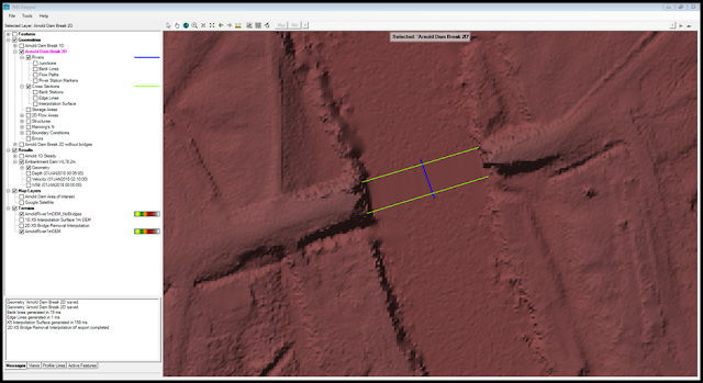
In this screen shot, Cameron has drawn a river reach with cross sections on either side of the bridge:
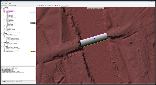
This process can be repeated with additional reaches for any other bridges in your terrain. The following screen shot shows the interpolation surface created by the bounding cross sections:
And the final image shows interpolation surface on top of the terrain to blend out the bridge:
Let us know what you think or if you have other suggestions for improving these processes.
And a happy 2019 to all of the fellow HEC-RASlers around the world!


Comments
Luis A Partida
on January 8, 2019Yea i have been doing this especially back when culverts (lateral weirs) couldnt be connected to cells that were not adjacent (apart from the worm hole method) for some time now. This was well written and explained
Chris Goodell
on January 11, 2019Thanks for the post Krey!
Unknown
on May 2, 2019Hi I have a question. When creating a new terrain (in order to remove bridges, etc) is it necessary to check the 'merge inputs to single raster' box? I've done this process with both the box checked and unchecked and I got slightly different results… Will this have any impact on my modeling?
Chris G.
on May 2, 2019No need to do this, but if you do, all of the input rasters will be merged and use a single grid cell size. So if you have different resolution in your input rasters, they will be resampled to a common resolution. That would explain the difference.
Arnaud K.
on September 16, 2019Hi, I'm a little late to the party here, the process you describe works perfectly well, thanks for this post. Do you think that there could be in the future the option to impact directly the levels in the mesh ? For example add an option in the refinement regions to impose a min. or max. level to the cells?
Chris G.
on September 16, 2019That would be a very useful feature. Hopefully they add that in. The next version (5.1) will have some very nice new features!
Add Your Comment