Weir Equations in HEC-RAS
Written by Chris Goodell | July 11, 2016
HEC-RAS has the ability to simulate flow at hydraulic controls in a variety of ways.
Bridges, culverts, inline structures, lateral structures, and SA/2D area connections can all act as hydraulic controls. Effectively, they break up the conservation equations used between cross sections in a 1D reach and/or cells in a 2D area with empirically derived (and usually very stable!) equations. Weir equations can be used to define flow over an obstruction and are available with all of the 5 hydraulic controls identified above. However, there are a number of options to consider when selecting simulating weir flow in HEC-RAS. HEC-RAS approaches weir flow with three different cases: Ungated Inline Weirs, Ungated Lateral Weirs, and Gated Weirs. They all begin with the same standard equation:

(1)
Where: Q = discharge, C =weir coefficient, L = weir crest length, H = Energy head over the weir crest.
But each of the three cases apply the weir equation slightly differently.
Before I continue, I should discuss the difference between the weir coefficient and the discharge coefficient. I see both of them used interchangeably, but they ARE different. The weir coefficient (as shown above in the weir equation) is a lumped parameter that includes the discharge coefficient, the gravitational constant, and constants based on geometric properties.

(2)
Where Cd is the discharge coefficient.
The discharge coefficient is dimensionless and therefore it is the same in both English (U.S. Customary) Units and SI Units. The weir coefficient, since it is a function of the gravitational constant, is not dimensionless and therefore has different values depending on which unit system you are using. For example, a weir coefficient (C) of 3.00 in English Units would be 1.66 in SI units. But both share the same discharge coefficient (Cd) of 0.56. For convenience, to convert an English weir coefficient to an equivalent SI weir coefficient, multiply the English weir coefficient by 0.552.
Be very cautious when considering C versus Cd. They are different but are often mistakenly used interchangeably. In fact, you’ll see the coefficient Cd labeled occasionally in the HEC-RAS software and literature when discussing weir coefficient.
Ungated Inline Weirs.
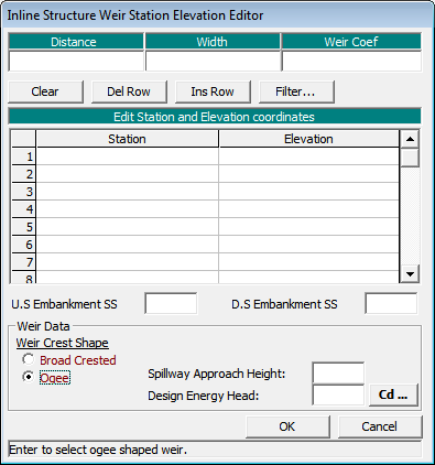
When defining inline flow over an “ungated” obstruction (bridge, culvert embankment, inline structure, SA/2D area connection), you have two options for computing weir flow: Broad Crested and Ogee.
Figure 1. Inline structure weir embankment editor.
Both use the same standard weir equation presented above in equation (1).
The only difference between the Broad Crested Option and the Ogee Option is that for the Broad Crested option, the user enters a weir coefficient for C. For the Ogee option, the user enters a spillway approach height and the ogee’s design energy head, and HEC-RAS will compute the weir coefficient for you. This may sound convenient, but as the name implies, this option should really be used only for ogee-shaped spillways. And you would have to know what the design energy head is, a design parameter that is not usually easy to come by, unless you have the hydraulic design report for the spillway. With both options, submergence reduction of the discharge is automatically calculated with their own respective methods (FHWA ,1978 for broad crested, and COE, 1965 for ogee).
Ungated Lateral Weirs.
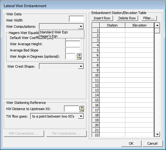
Lateral weirs are entered in the lateral structure editor. Inside the lateral structure’s weir embankment editor, you’ll see two options for weir computations: Standard Weir Eqn. and Hager’s Eqn.
Figure 2. Lateral Weir Embankment Editor.
In version 5.0.1, the Standard Weir Eqn. provides four options for the weir crest shape: Broad Crested, Ogee, Sharp Crested, and Zero Height. Caution! Zero Height is NOT used when Standard Weir Eqn. is selected. This is a bug and will most likely be fixed for future versions. If you do select Zero Height and Standard Weir Eqn. together, HEC-RAS will just use the weir coefficient you provide with the broad crested methodology. Sharp Crested is not fully functional in Lateral Structures for version 5.0.1. You’ll notice that no additional input options (like Rehbock and Kindsvater-Carter, as discussed under the next section, “Gated Weirs) are available when you select Sharp Crested in the lateral weir embankment editor. My guess is that if you select Sharp Crested, it too will default to the broad crested methodology.
Broad Crested and Ogee work the same as with the ungated inline structures.
With Hager’s Equation, all four weir crest shapes are available, including the zero-height weir. The same weir equation is used, but an adjusted weir coefficient is computed based on physical and hydraulic properties. Each of the four weir types has its own method for computing the adjusted weir coefficient. There is an input box for “default weir coefficient”. This is only used for the first iteration of solving Hager’s Equation. Since Hager is a function of hydraulic properties, it must be solved in an iterative fashion. After the first iteration, the adjusted weir coefficient will be computed and used. Page 8-18 of the Hydraulic reference manual discusses Hager’s equation and how the adjusted weir coefficient is computed.
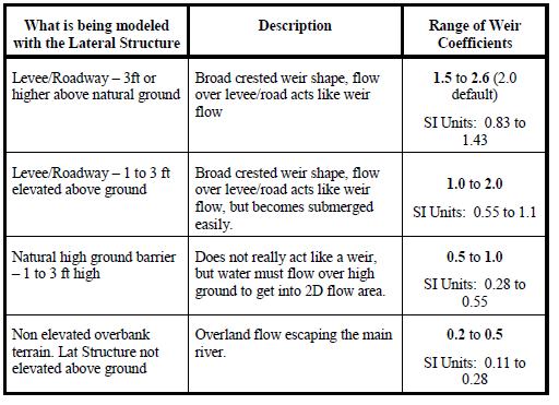
Zero-height weirs are used for cases where flow will leave a channel laterally, but there is no defined obstruction or hydraulic control separating the two. Commonly this is used to simulate flow from a main channel up a tributary that is being modeled using a lateral structure and a storage or 2D area. The HEC-RAS 2D manual has a table of lateral weir coefficients (Table 1).
Table 1. Lateral Weir Coefficients (from the HEC-RAS 2D Manual, page 3-50).
Notice the last category is “non elevated” overbank terrain. If you wish to use the weir coefficients in this table to simulate a non-elevated weir, do not use the Zero-Height weir. That is strictly for Hager’s equation and Hager’s method automatically computes the weir coefficient. Instead, use the broad crested standard equation and enter in the non-elevated weir coefficient there.
Gated Weirs.
When modeling gated spillways at inline structures or lateral structures, users can provide a weir coefficient for flow over the spillway when the gate is completely opened, and out of contact with the flow (Figure 3). This is different from the discharge coefficient used for flow over the top of the inline structure (Figure 1).
Figure 3. Inline Gate Editor
With gated spillways, the user has three options for the weir shape: Broad Crested, Sharp Crested, and Ogee (Figure 4). Broad Crested and Ogee work the same as previously discussed. The Sharp Crested option also uses the standard weir equation but gives you three options for determining the discharge coefficient: user-entered, compute with the Rehbock equation, or compute with the Kindsvater-Carter equation. For both the Rehbock and Kinsvater-Carter methods, the weir coefficient will be computed independently at each time step. So you can have a varying discharge coefficient for varying heads.
Figure 4. Inline Gate Editor.
The Rehbock equation for the discharge coefficient was developed for rectangular weirs and is as follows:
(3)
Where P = Spillway approach height. This value must be entered to use the Rehbock equation. HEC-RAS will then compute the weir coefficient, C using equation (2). According to Ippen (1950), this equation holds up well for values of H/P up to 5. And it performs with fair approximation for H/P values up to 10.
The Kindsvater-Carter method was developed in English units only and is as follows:
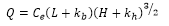
(4)
Where Ce = effective weir coefficient, ft1/2/s
kb= a correction factor to obtain effective weir crest length, ft
kh= a correction factor with a constant value of 0.003 ft
The effective weir coefficient, Ce is a function of two ratios: L/B and H/P,
Where L = Weir crest length
B = Average width of the approach channel
H = Energy head over the weir crest
P = Spillway approach height
Ce is a function of both the relative width and relative depth of the approach channel and is taken from the following chart (note that the chart uses the variable h1 for H. They are the same):
Figure 5. Effective Weir Coefficient
kb is used to determine the effective length of the weir crest and is a function of the relative width of the approach channel. It is taken from the following chart:
Figure 6. Correction factor kb.
To use the Kindsvater-Carter method in HEC-RAS for a gated spillway, first select the weir shape as “Sharp Crested”. Then select “Compute with Kinsvater-Carter eqn as the Weir Method. You must then choose a relative approach channel width (L/b) and enter the spillway approach height, P (note, b is used in the HEC-RAS Inline Gate Editor for B. They are the same).
Figure 7. Kindsvater-Carter Weir Method.
Remember, the Kindsvater-Carter equation was developed and is presented here in English units. When using SI units, HEC-RAS will automatically convert the units appropriately. So you can still enter a spillway approach height in meters if you are using SI units.
The Kindsvater-Carter weir equation is built for rectangular weirs and “is particularly useful for installations where full crest contractions or full end contractions are difficult to achieve.” (USBR 2001) More information on the Kindsvater-Carter equation, including its limitations, can be found here:
http://www.usbr.gov/tsc/techreferences/mands/wmm/chap07_06.htmlReferences:
Federal Highway Administration (FHWA), 1978. Hydraulics of Bridge Waterways, Hydraulic Design Series No. 1, by Joseph N. Bradley, U.S. Department of Transportation, Second Edition, revised March 1978, Washington D.C.
Ippen, A.T. ,1950. Channel Transitions and Controls, Chap. VIII in Hunter Rouse (editor): Engineering Hydraulics,” John Wiley & Sons, Inc., New York. pp.496-588.
U.S. Army Corps of Engineers (COE), 1965. Hydraulic Design of Spillways, EM 1110-2-1603, Plate 33.


Comments
Unknown
on July 15, 2016Can a stepped spillway simulation performed with HEC-RAS?
Chris Goodell
on July 15, 2016HEC-RAS is not a suitable tool to simulate detailed hydraulics down a stepped spillway. However, to the extent you can simulate the effect of a stepped spillway on the upstream energy head using the equations above, it can certainly be part of a HEC-RAS model.
Rodrigo
on September 16, 2016Hi Chris……….My name is Rodrigo and i am from Chile.
I have a question about modelling gated weirs with ogee shape.
The downstream section of the weir is the natural stream section or its located at the end of the ogee profile??
Best regards
Rodrigo
on September 21, 2016Chris
In a ogee crest spilway what is the meaning of the with parameter?
Chris Goodell
on September 22, 2016I don't know what the "with" parameter is. Please clarify.
Toby
on December 12, 2016Hi Chris,
Do you have any insight into the new "Overflow Computational Method" for lateral structures into a 2d area (e.g. Normal 2D Equation vs. Use Weir Equation)? If one is trying to model a 1d/2d connection where there is overland flow and a non-elevated overbank, what might be the benefits or shortcomings of each method? What would you set your weir width to for an overland flow situation with a low weir coefficient chosen from the table above? Any other advice to reduce 1d/2d flow errors over lateral structures?
Thanks!
Chris Goodell
on December 12, 2016Toby-Great questions! the quick answer is: "if it is acting like a weir, model it as a weir, otherwise model it with the 2D equations." However, as with many things in RAS, there's a lot more nuance involved. I like to think about the input data required and how confident I am with it. The weir equation requires a very subjective weir coefficient. The 2D equations do not. Although the 2D equations come with their own subjective assumptions and limitations: terrain quality, theta value, eddy viscosity, full momentum or diffusion wave, etc, etc. So for me, if it's an elevation connection, I'd lean towards the weir. If it is overland flow, I'd lean towards using the 2D equations. HEC does caution against using the 2D equations if the connection is elevated such that water going over it will experience "free fall" (i.e. a waterfall). The 2D equations can't handle that. This might just be another good example where you try them both as part of your sensitivity analysis. Also, keep in mind that the weir width is not used at all in the computations (weir or 2D equations). It is purely there for graphical purposes. As far as advice to reduce 1D/2D flow errors over lateral structures: Break up long lateral structures into multiple smaller ones. Be careful not to use too high of a weir coefficient. Do not have cells adjacent to the lateral structure that reside completely on the slope of the levee/berm/whatever you're modeling with the lateral structure. I typically like to take the cross sections right to the peak of the high ground feature, but start my 2D cells at the toe of the feature. Good luck!
Emmanuel Jjunju
on June 12, 2017Hello,
if you look at the "Storage Area Connection Weir Data", there is a field for input of "Standard Weir Equation parameters". Under this it is written, Weir coefficient (Cd). Now from the explanation Cd(discharge coefficient) whose relationship to C is C=2/3*Cd-(2g)^(0.5) [by the way some books have [C=2/3*Cd-(2/3*g)^(0.5)] which is confusing. have the makers of HEC-RAS made a mistake? did they mean C or Cd?
Emmanuel Jjunju
on June 12, 2017My conundrum regards the Weir coefficient in the “Storage Area Connection Weir data”
Q1: It is written, Weir coefficient (Cd). Now from your explanation Cd is the Discharge coefficient and C is the weir coefficient. This is very clear. Have the makers of HEC-RAS made a mistake? Did they mean C (Weir coefficient) or Cd (The dimensionless weir coefficient)? You wrote “In fact, you’ll see the coefficient Cd labeled occasionally in the HEC-RAS software and literature when discussing weir coefficient. “. Is this one of these occasions?
The HECRAS reference manual also sometimes refers to C as coefficient of discharge, further compounding the problem.
Q2: You also wrote that C=2/3*Cd-(2g)^(0.5) but some references have [C=2/3*Cd-(2/3*g)^(0.5)] ; This is confusing.
Chris Goodell
on June 12, 2017As mentioned in the post, HEC mistakenly uses Cd in the software occasionally when they actually mean C. All weir coefficients you enter in RAS are the non-dimensionless C values (i.e. they are different for English versus SI units. So be careful with this.
Chris Goodell
on June 12, 2017It is as written in the post. The following article does a good job deriving the weir equation if you want verification: http://www.codecogs.com/library/engineering/fluid_mechanics/weirs/discharge.php
Vargas Ramiro
on October 10, 2017Hi Chris,
My name is Ramiro, I work for Hydro-Quebec, Quebec, Canada.
Sorry about my english 🙂
I'm a little lost on what values to use on modelling a radial gate in a 2D model I'm working on.
I read (HECRAS 5.0 Reference Manual – page 8-8) and I found the equation:
Q=C*(2g)^0.5*W*T^TE*B^BE*H^HE where Q=flow in cfs
I'm using SI units for my model, and in the Connection Gate Editor I need to provide several values for modelling the flow ( Radial discharge coefficient, Trunnion exponent, Openning exponent, Head exponent, Trunnion height) my question is: where I can fin the equation below in SI units and which values to use for those coefficients?)
Thanks a lot!
Chris Goodell
on October 12, 2017HEC put that equation in that way to provide more flexibility for how to compute flow through a radial gate. Most people ignore the added terms by putting in 0 for TE, 1 for BE, and 1/2 for HE. I believe they are all unitless, so should be the same for SI and English units. Hope this helps-
Chris
Vargas Ramiro
on October 13, 2017Yes it helps! I calculated (by hand) the flow in both systems (english and SI) with the HEC equation and yes the terms are unitless. Thanks!
Anonymous
on October 21, 2017Hi Chris,
I have a question about what value weir coefficient to use for a SA/2D Connection? I am modeling a 2D mesh into a Storage area and have a SA/2D Connection as a weir set to the elevation of the terrain for the connection?
Thanks,
Chris Goodell
on October 21, 2017For 0-height weirs, the weir coefficient should be quite low. Check Table 3-1 on page 3-50 of the 2D HEC-RAS Manual. While these values are presented for lateral structures, I think it will give you an idea of where you should be for your weir coefficient for your situation.
Anonymous
on October 21, 2017What are thoughts about the option between "compute as curves (faster)" or "compute flow each time step"?
Chris Goodell
on October 23, 2017Compute as curves makes htab tables out of the weir. This is faster, but comes with a little bit of error (potentially). Usually the error is insignificant. Computing flow each time step is a more precise way of getting weir flow, but takes longer, as the software has to recompute the flow each time step. Most likely you won't notice the slowdown.
Anonymous
on October 26, 2017Hi Chris,
Even when working in metric units, when we hover the mouse over Weir Coefficient in the Deck/Roadway Data Editor or Inline Structure Weir Station Elevation Editor, the pop hint still shows the weir coefficient range for broad crested weir as 2.5-3.1 and Ogee 3.1-4.0. Is that a bug? Shouldn't be in the range of 1.3-1.71 for broad crested and 1.71-2.21 for ogee? Thanks.
Chris Goodell
on October 27, 2017Yes, that's a bug. I'll let HEC know to fix that. Thanks!
Anonymous
on December 19, 2017Hi Chris,
I'm new to the RAS Solution, so my apologies if this isn't the appropriate spot for this question.
I'm in the process of designing rock weirs, vortex "U" weirs. It appears that HEC-RAS can only model in-line or perpendicular weirs that completely span the creek at one station. Is there a method to accurately model vortex weirs? I really need accurate water surface elevation information for a proposed diversion.
Thanks.
Chris Goodell
on December 20, 2017Sounds like a great 2D application. You could make a 2D area in the zone where you have your weirs, then use SA/2D Area connections to simulate your weirs in whatever shape you wish.
Anonymous
on December 20, 2017Thanks for the quick response, Chris. I am aware of the 2D capabilities of HEC-RAS, but have yet to experiment with them. I'll give it a shot. Thanks again.
Anonymous
on January 10, 2018Hi Chris,
When putting a weir in my model, I want to set its crest at critical depth. Is their any way I can see critical depth in the result files? In the result files, I can turn on the critical depths for the x-sections but not for the weir. Is it possible? Thanks.
Anonymous
on January 10, 2018Just a clarification on seeing critical depth for weirs – this is with relevance to inline structures.
Chris Goodell
on January 15, 2018I'm curious why you want to set your crest to critical depth? Not a critique…just wondering. Why don't you run the model first without the weir, but instead with a cross section in the same location. Get the critical depth elevation from that run, then remove the cross section and replace it with a weir with the elevation of critical depth.
Anonymous
on January 17, 2018I want to place a weir (an inline structure) in my channel (irregular x-section) and I want to make sure that it acts as weir i.e flow passes through critical depth over the weir. I think you can easily put in a weir with crest height so low that it does not effect the flow and the flow does not pass through critical depth. Basically, I am looking for minimum height of the weir that I can use without effecting the water levels upstream.
Chris Goodell
on January 17, 2018Theoretically a weir with any height to it will affect water levels upstream. But why not give it a try. Use progressively shorter weirs until you don't see a significant change.
Anonymous
on January 30, 2018Hi Chris, Am considering damming a section of a river using a weir to abstract water for domestic supply. Our client is interested to know the effect of building this weir on the upstream side of the river and if there will be any flooding during the max design flood which is 1:100. I was wondering how I can simulate this using HEC-RAS. Our surveyor is going to site soon to do a topo survey of the area. what would be the most important data I could advice he collects for this exercise? Please advice. Thanks
Chris Goodell
on January 30, 2018HEC-RAS is a great tool for this type of analysis. Based on your question, I assume you are new to HEC-RAS. My advice would be to hire a qualified and experienced HEC-RAS modeler to do this for you. Trust me, it will save you money in the long run and make your client happy. That person would know all of the requirements for setting up and running this analysis. Plus, every site is different, so before recommending what survey data is needed, one needs to know what survey data is already available, it's quality, as well as site-specific conditions that will have an influence on the hydraulics of the system, among many other things. And finally, damming a river with a weir is not a trivial thing. You want to make sure to get it right.
Anonymous
on February 6, 2018Hi Chris,
Thanks for your feedback. Actually I have used HEC-RAS before but in a class work. Its not really damming the river maybe I used the wrong words, but rather constructing a short weir across the river(2-2.5m high). I was just interested to know what other data I might need for this specific task besides the channel geometry,.
Anonymous
on February 12, 2018Hi Chris
When using the 2D connection as a weir embedded in 2D grid, is flow over the weir based on energy level or water level? I'm just cross-checking some HEC 2D results and am trying to resolve some inconsistencies.
Thanks
Craig
Entura
Chris Goodell
on February 12, 2018That's a good question. I don't think it is explicitly stated in the manual. I would assume that to be consistent, it uses the energy level. But honestly I don't know for sure. Let us all know if you find out. I'll do the same…
Chris Goodell
on February 12, 2018Just heard back and the answer is RAS uses the water surface elevation as the headwater reference for SA/2D area connection weirs.
Brian Brown
on February 27, 2018I have a small dam that has 2 secondary discharge channel in addition to the primary discharge pipe. The two secondary discharge channels go in two different directions. I am modeling a dam breach and have to had a 1D model through the dam breach, then can switch to 2D for the overland flow through a subdivision that is needed to be mapped. I model the one secondary discharge as a lateral weir leaving the system (and into a 2D flow area) and leave the remaining primary and other secondary discharge as part of the main dam. If the dam were breached the initial secondary discharge would not be part of the breach flows, therefore I need to remove it from the system for the breach. nothing is gated or controlled, it is all gravity. I can get the entire model to work including the 1D unsteady, breach and 2D connections. I have modelled all the weirs as rating curves. Where I am having a problem is that my lateral weir requires that I have a physical weir shown in the model or it will not transfer the flows. However, when I do this, it sets a tailwater elevation that is more than 0.8' higher than the incoming flow elevation. Where this become a problem is that my 2D flow now routes around the dam in a manner that it cannot at the elevations it should be at. This causes additional flow in areas where it should not be. How can I control the tailwater elevation for lateral weirs?
I am using 5.0.3. Would also like to see how you can breach a dam in 2D without having to go back to the 1D cross-sections. Guess i'll need to wait for future version…
Thanks for any advice assistance.
Brian
Chris Goodell
on February 27, 2018Brian- too much for me to type a response. Why don’t you give me a call at 503-793-2700.
Anonymous
on March 14, 2018Hi Chris, i'd like to ask you something about radial gates in the inline structure. I have to simulate a weir with three radial gates 10 m x 10 m in steady flow conditions in the case of all the gates opened.
When i finish the simulation and i look at the inline structure output table i see that the whole discharge is splitted in Qweir and Qgates. I don't understand this thing because i'm simulating a weir with three gates totally opened: in my mind it is like a weir without gates.
Thanks for any advice assistance
Mirko
Chris Goodell
on March 14, 2018Even though the gates are fully opened RAS still considers that gate flow. Weir flow would be what’s going over the inline structure.
Bob Elliot
on April 19, 2018Chris, what about user-defined rating curves, such as for a gate in an inline spillway? Does RAS assume you are using Energy Head to define the rating, or Water Surface (hydraulic head)? Examination of results seems to indicate it's using Energy, but what if the gate rating provided (say from a dam operator) is based on WS? I think we'd prefer it use WS rather than Energy, or at least provide an option to switch. Thanks!
Chris Goodell
on April 21, 2018That would be a nice option!
Vargas Ramiro
on May 25, 2018Hi Chris!
I'm Ramiro from Montreal. I work for Hydro Québec.
I have a 2D model and I'm having a problem with conservation of flow.
I have 2 boundaries condition upstream (total flow of 6500 mcs), an inline structure located 5 km downstream and a downstream boundary condition 10 km downstream from there.
The problem I have is I'm losing flow from upstream boundaries conditions to my in line structure, about 7%-10% less flow pass through the in line structure (6000 mcs) . I have the good flow 6500 mcs at the downstream boundary condition. I made 2 geometry files : One with the in line structure with rating curves and another one with 10 radial gates. Both give the same result.
The levels are steady and I have no loses anywhere else.
Do you have any idea how I can improve my simulation?
thanks a lot!
ali imo
on May 27, 2018Hello chris! great work on this blog, it helped me a lot during my study. I'm doing a dam break analysis study and I'm having a problem with lateral structures, the model is a combined 1D-2D model where the channel is 1d and both the right and left floodplain are 2d, they're connected with lateral structures. the problem is that the WSE and EG are acting weird and doing these little steps in various locations in my reach https://imgur.com/4QXcugl and these are the only places where the water overflows from the river to the floodplain. I've tried: using very small timesteps (from 0.5s to 10s ), increasing HTAB points, small cross section spacing(15m). if you have any tips or hints that can help it would be greatly appreciated.
thank you
Ali
Vargas Ramiro
on May 28, 2018Hi Chris! I'd like to ask you about conservation of flow in a 2D model.
I have a model with 2 boudaries upstream with an constant flow going into the model, a dam with 10 radial gates in the middle and 1 boundary condition downstream. The proble I have is I'm losing 7% of flow:
Upstream flow: 6500 mcs, fow through the dam 6000 mcs, Downstream flow 6500 mcs. Did you hear about this before? Thanks!
Clark
on May 29, 2018Greetings,
I am having stability issues while trying to run a steady flow model with a lateral weir. The downstream end of my model is a constrictive rating curve. Then 200 feet upstream of the end of the model is a 100 foot lateral weir overflow with the TW connection set to “out of system”. I am trying to determine the elevation of the channel at various high flows. The weir has a sloped height of 2 to 5 feet. When running the model I get “Flow Optimization Failed to Converge.” I have tried inputting the resulting flows into the “initial split flow optimization” of the steady flow data but that just makes the next results worse. I am getting flows leaving the weir much greater than my steady flow input.
I have tried various weir coefficients ranging from 1.5 – 3.0, with similar optimization failures. Should I go to an even lower coefficient based on the weir geometry? I have tried both the standard weir equation and the Hager’s eqn. Based on my model set up is one method preferable? If I used the standard equation should I have separate geometries with different coefficients for different flows?
I have 50 foot cross section spacing. Is there a place along the channel (above weir, through weir, below weir) where I should have greater or smaller cross section spacing?
Any advice or thoughts would be greatly appreciated!!
Thanks,
Clark
Kirtan Adhikari
on November 1, 2018The HECRAS 5.05 version has an option to compute weir coefficient of Ogee weir by supplying Spillway Approach Height and Design Energy head. for example. I supplied 15.98 and 10 respectively and weir coefficient was 2.17. which equation is invoked for calculation?
Bikash
on November 20, 2018Hi,
I found two ways to model inline structures (Eg. Broad crested and Ogee weir). One approach would be by creating the broad crested profile with the input of series of cross section while as another approach is to add inline structure on the channel section and define broad crested weir. Would you please inform me which method is more accurate ?
Unknown
on March 15, 2019For a spillway, how downstream conditions taken into account? For example for a semi submerged crest…
Chris Goodell
on March 18, 2019RAS uses a flow reduction factor based on percentage of submergence. You can check the hydraulic reference manual for more detail.
Peter
on June 6, 2020Hello, I´ve got a model, with 2 connected 2D Areas. The simulation works stable. One 2D Area includes the river and as a lateral Connection i created a SA/2D Area connection (Weir) to flood the 2nd 2D area as (a polder area).
Is there a possibility to find out which maximum storage Volume of all cells together have (after simulating the flood)?
I only can find the data for one cell in Ras Mapper, but there are over a 1000, I cant add them handish.
Thx and greets
peter
Chris Goodell
on June 8, 2020Hi Peter. Unfortunately there is not yet a volume map in RAS Mapper available to us. You may be able to get what you’re after in the computation log output file. At the end of that text file, you’ll see some information on volume accounting. Not sure if that is what you are after, but may be helpful to you. If you have some programming skill, you could write a script to retrieve from the plan hdf file the max water surface elevation for each cell, along with each cell’s elevation volume relationship. Then the script could determine volume for each cell and sum them together for teh total. Outside of that, I’m afraid there’s no way in the current version (that I’m aware of).
Mike
on September 15, 2020Hi Chris. I’m using v5.07 and having issues with the lateral weir and hoping that you can give me some insight. I’m working on creating a duplicate effective of an old HEC-2 model that used split flow to simulated losses off of the left bank. The effective model returns the flow to the river channel at a cross section about 3 miles d/s of the start of the reach. The output from the effective model shows that the exact amount calculated lost to the split flow is deducted from the next downstream cross section flow so that the math balances and this continues with each successive cross section until the flow returns. I’m using the lateral weir option in RAS and unfortunately I am never able to get the flows to balance. What is calculated as lost to the lateral weir isn’t what is subtracted from the flow of the upstream cross section and the number get rather strange. At one series of cross sections, there’s about 2500 cfs across the u/s XS, 6000 cfs calculated as going across the lateral weir and then the next d/s channel XS still has 2490 cfs in it. Conservation of mass, this isn’t! I’ve optimized the flow at each XS and tried just about every thing that I can find. No luck. Any hints on how to fix this? Thanks for any help you can provide!
Chris Goodell
on September 22, 2020Hi Mike. Unfortunately, this sometimes happens. You can try adjusting your initial flows for each reach to try to match where RAS is trying to go with the flow splits and see if that helps to optimize. If that doesn’t work, I’ll create a quasi-steady model using the unsteady engine (constant discharges for the inflow hydrograph). The unsteady engine handles flow splits over lateral structures much better than steady flow.
Toby
on September 22, 2020Do lateral structure use a submergence ratio, like an inline weir or bridge, to slow flow due to a backwater condition? I can’t find any mention of this in the Reference manual. I would assume it does, but want know more.
Thanks!
Chris Goodell
on September 22, 2020Yes it does for weir and culvert flow. And can be a source of instability which is why the submergence decay exponent is available for you to adjust if needed.
Indi
on November 13, 2020Hi Chris,
I followed step by step procedure to model inline structure from the HEC-RAS manual, but still, it is showing the error “Gate opening data incomplete”. In reality, the weir does not have any gate opening. So, how can I model the weir in that scenario?
Thankl you.
Chris Goodell
on November 17, 2020Just don’t include a gate for your inline structure. You don’t have to have one.
Indi
on November 25, 2020Thank you.
Mi
on April 28, 2021How can i simulate a stepped weir with HEC-RAS 2D? I understood that it is not possible to simulate it correctly but how can i consider a stepped weir in a 2d model? Thanks!
Chris Goodell
on April 28, 2021You would need VERY close cross sections. But keep in mind, RAS is not the best tool to use for spillways. Spillways normally exceed the 10% maximum slope guidelines for RAS. Furthermore, RAS does not directly compute bulking of the water surface due to air entrainment, cross waves, splashing, etc-all things that can be prominent for spillways. But if you place your cross sections close enough, you can get RAS to work on a spillway (stepped or otherwise), but just understand the result you get may not be very accurate.
Vojtěch Kouba
on April 28, 2021Thank you Mr. Goodell for this guide. At Czech republic we using Cd and your paper help me using right coeficient. Thank you again for HECRAS. I like HEC family SWs.
Sheilla
on June 6, 2021Hi Chris,
I have a dam am modelling..am new to Hec Ras…but the spillway is an ogee type with a slanting upstream face and it has a 2 by 2m approach channel close to the bottom, with gates at the end. I don’t see where I can specify these in Hec Ras model ( The bottom channel and ogee shape)…please help me out. Thanks so much
Chris Goodell
on June 7, 2021The ogee shape is specified by how you pick your discharge coefficient. Not sure where your bottom channel is in relation to the spillway by your description, but is this something that you should include in your cross section(s)?
Sheilla
on June 6, 2021I also want to know why my animation function can’t work…I’d want to visualize the water flow.
Chris Goodell
on June 7, 2021Three things to check if you’re having animation issues. Do you have an unsteady flow model? If so, did it complete without crashing? And is your detailed output interval small enough?
Ben Kladder
on August 2, 2021Hi Chris, we are modeling a water control structure (WCS) as an inline gate to model drawdown of an impoundment for a dam removal project. The WCS will have stoplogs removed over time to control the drawdown. I’ve chosen a sharp crested weir for the gate which seems appropriate. RAS suggests a weir coefficient of 3.2. I want to check the discharge coefficient using the Rehbock equation (its a rectangular gated weir), however our spillway approach height varies over the drawdown period as stop logs are removed, and is essentially zero when all stop logs are removed (invert of the WCS/gated stop logs is just above the final channel elevation). When I use average model results for the midway point of the drawdown, the Rehbock equation gives me a discharge coefficient of about 0.7 to .9, which is much different than 3.2.
Chris Goodell
on August 2, 2021Ben, the Rehbock equation in it’s standard form provides a discharge coefficient. To get a weir coefficient (for use in RAS), you would need to multiply the discharge coefficient by (2/3)*(2g)^0.5. That should get you into a reasonable range. I.e. 0.7 times (2/3)*(2g)^0.5 is 3.74.
gaagai aissam
on October 26, 2021Hi Chris Goodell
I work about the dam breach by HEC RAS 6.1. version. but when I click to the compute, it appeare this ERROR:
weir maximum submergenece ratio is not set
and this Option in HEC RAS 6.1 dont exist
please you can helpe me to resodre this problem and thank you
Caz Richards
on December 7, 2021Hello, I’m experiencing the same problem as gaagai aissam. I’ve built a dam breach model in HEC-RAS 6.1 using two approaches; i) a storage area for a reservoir with cross-sections for the reach, ii) cross-sections for both the reservoir and reach. Both use an inline structure for the dam breach. However, when I try to run an unsteady flow simulation, an error indicating the input data is incomplete appears, saying “Weir maximum submergence ratio is not set”. I’ve tried troubleshooting this, looking at HEC-RAS example projects, looking through all the menus and re-reading manuals and document TD-39. However, I cannot find any menu or window that allows a submergence ratio to be set. Does anyone know of a fix or an alternative approach? My project is too large really to run a 2D model as an alternative, so I’m really stuck. Thank you!
Chris Goodell
on December 20, 2021In Version 6.1, Inline structures have a default setting for max weir submergence, but unlike bridges, there is no place for you to enter that data. RAS just automatically uses the default value of 0.98. You can either try deleting the inline structure and re-enter it and see if that works, or you can edit the geometry file manually in a text editor where you can type in your max weir submergence.
To manually add in your max weir submergence, follow these steps:
First Close HEC-RAS.
Make a backup copy of your geometry file, just in case you make a mistake.
Then open your geometry file in a text editor (like Word, Notepad, Wordpad, etc.), and search for the inline structure.
In the comma delimited numbers below the line that says “IW Dist, WD, Coef, Skew, MaxSub, Min_El, Is_Ogee, SpillHt, DesHd”, you should add the number 0.98 (or whatever max submergence you want to use) in the 5th position.
Save the text file with 0.98 added in and close it.
Then open HEC-RAS. It should work after that.
Nathan Millingar
on January 20, 2022Hi Chris,
We have two 2d flow area connections (required because one has precipitation on it). The are connected by 2d flow area connections modeled as weirs. One of these connections crosses a channel, while the rest are in the overbank. Our results show a significant loss across the connection in the channel (roughly 1.5 feet). I’ve tried tuning the weir coefficient to have the WSEL match, but as you’ve said earlier, the coefficient is adjusted by the program. Do you have any recommendations for my issue? Any way to override the coefficient iteration? Thanks so much!
Saba Ghotbi
on January 24, 2022Hi Chris,
I have a question for gated spillway when the gate has a large opening. If the ratio of upstream water surface to the gate opening is less than 1, the flow through gate opening is calculated as weir flow. So, I guess in this condition all types of gate are identical.
Question:
If at the same condition (large opening), the submergence begins to occur, which equation is used for the flow calculation?
Does Hec-ras compute flow using the weir flow with submerged coefficient? or just uses the gate flow equation under submergence condition?
Thanks
Chris Goodell
on January 28, 2022If the headwater is below the gate lip, RAS will use the weir equation and apply a submergence flow reduction factor depending upon the degree of submergence. If the headwater is above the gate lip, than it will use the sluice gate equation until the downstream water level increases above the gate lip, where it will then transition to orifice flow. A transitionary equation is used to smooth the change from sluice gate to orifice gate flow.
Chris Goodell
on January 28, 2022Nathan, the weir coefficient is constant if you use the broad crested weir option. Just put in the value you want and RAS will use it for the whole simulation. I’ve found that for non-weir type 2D connections, I need to really push down my weir coefficient to avoid overestimating head loss. Don’t be suprised if you are down in the 1 or lower range (US units) to get it to give a reasonable answer.
DEVANAND M R
on February 21, 2022Hi Chris, I am doing a check-dam analysis. I am dealing with low flows coming into a weir. while I am simulating the weir is full at the beginning itself. I want to know till what flow the weir will obstruct it and when it overflows what is the discharge at d/s. whatever the flows I am passing, it is reaching at d/s, taking the weir as full level and passing the flow. i want weir to obstruct the flow condition. please help me with it.
thank you
Chris Goodell
on March 4, 2022Hi, when you run an unsteady model, RAS first runs a steady flow profile to set up initial conditions, so it naturally starts full behind the dam. In order for the water to start low behind the dam, you have to provide an outlet condition at the dam the releases the same amount of flow you have for initial conditions. An easy way to do this is with pilot flow, but you could also add a low level culvert or gate to do the same thing.
GeorgeK
on April 18, 2022Hello again, in the first comment the question was if HEC-RAS can perform a stepped spillway simulation, and the answer was that it cannot. Is this still the case? If we use the 2D SWE-ELM equations with the turbulence set to non-conservative and a grid aligned in a way that cells borders are exactly at the ending of the steps? Would we still under evaluate the energy dissipation?
Another thought I had, was to compute the energy dissipation down the stepped spillway by hand and then find a manning’s n value that would produce the same energy dissipation in the HEC-RAS model. Of course, there must be different values depending on the flow. The only other alternative would be to use a CFD software for the spillway and then use the output of that as an input for the downstream part of the HEC-RAS model.
Chris Goodell
on April 18, 2022George, it depends on the objective of your study. Are you trying to determine accurate representations of the water surface profile down the stepped spillway? Do you need accurate velocity estimates at the toe? If so, I don’t think RAS is the tool for this. The primary deficiencies of RAS is that it simulates depth averaged velocities and doesn’t account for vertical accelerations-both very prominent in flows over spillways. If you are trying to simulate the overall head loss of flow going over the spillway to determine the reservoir stage, then I think you could manage this in RAS and your suggestions would be a good idea.
GeorgeK
on April 18, 2022Thank you for the immediate reply! My study is for a river restoration project. The river slope is too steep and I am trying to avoid having subcritical flow, because there is a bridge downstream of the steep slope and I would prefer to have supercritical flow at the bridge section. But I also need to determine the velocities and sheer stress of all the restoration section, in order to propose measures for the protection of the river bed.
I think I will use HEC-RAS for the rest of the river and manually compute the velocities and energy dissipation of the stepped spillway or use a CFD software package.
Thank you again!
Chris Goodell
on April 19, 2022Great idea!
Haqqan Uddin
on July 6, 2022Hi,
There is an error occured when going for steady flow simulation that is “Weir submergence ratio is not set” , what is it ?
Chris Goodell
on August 12, 2022This post explains it: https://www.kleinschmidtgroup.com/ras-post/weir_submergence_error_solved/
Ila
on September 16, 2022Thanks so much for you blog! I have what I (think?) may be a straightforward question for those with lots of experience.
I have a 2D model of a river reach with a low head dam/weir across the channel in about the middle of my study reach (which was built to maintain/control water levels upstream). It is an old structure but from the available information it has an ogee shaped spillway. For the study, we are looking at high flow conditions.
I am modelling it as a SA/2D connection, within my 2D area. When I select ‘weir equation’ for the overflow calculation, the WSE change over the weir is larger than what was observed during a flood event (i.e calibration event). I then changed it to use ‘Normal 2D Equations’, and the initial results for the high flow calibration event are closer to the observations. In the manual (subsection ‘Hydraulic Structures Inside of 2D Flow Area) I found the following, which makes sense and is consistent with my approach :”…..For a highly submerged structure, where the flow is not behaving like weir flow, the 2D equation will generally give better results, but the 2D equation is not as appropriate for traditional weir flow.”
My question/concern is about cell refinement to make sure that the 2D cells will ‘see’ the crest elevation of the weir, which is higher (by 1-2 m) than the adjacent terrain data.
There is discussion in the manual, including discussion of an example using a levee:
From the manual: “The 2D flow area mesh was modified to have cells on both sides of the levee lined up on top of the levee. This requires adding small enough cell spacing along the hydraulic structure centerline to get the correct detail. However, you do not want the cells to be so small that you have cells going down the levee embankment, such that these cells would be very steep. Steep cells on the back side of a levee could cause the model to have stability issues when flow overtops the levee (i.e., the flow may appear to be going over a water fall). So make the cells large enough to encompass the levee embankment slope and a little of the area away from the toe of the levee.”
However I am not sure I understand this fully. Let’s say my weir width is 3m, and the crest elevation is 102 (entered via the embankment station/elevation table). The river channel is wide (~300 m) and i had been using a mesh size of 10m around the structure. I enforce a breakline at the structure, so the cell faces align along the centre line of the weir. Do you know how HEC RAS assigns elevations to these cells, taking into account the entered weir embankment data? When I select the individual cells along the breakline, and look at the elevation information (in ras mapper), it does not reflect the entered weir crest elevation. My understanding is that hec ras computes an average elevation for each cell, and due to the large varation between the face along the crest and the face 10 m DS/US (say, 2 metres lower), the average elevation will be a lot lower and the effect of the weir will be ‘underestimated’. My thought is that I should use really small cells in a refinement region, such that an entire cell would be encompassed within the weir width (say, a 1 m cell spacing for a 3 m weir width). But then I also know there are stability issues with ‘steep’ cells, and that may be an issue?
Basically I am trying to see how HECRAS integrates the entered SA Connection geometry with the terrain, when the ‘2D equations’ are selected.
I apologize for the long post, but I wanted to try to explain the context well. Thanks in advance for any experience anyone can share!
Add Your Comment